64
64
NC2 0 - Manual - 01 - 2015
FUNCTION CHARACTERISTICS
Minimum operate time: 0.1 s
Range where the equation is valid:
[1]
1.1 ≤ I
NC
/I
N
>
inv
≤ 20
If I>
inv
pickup ≥ 0.15 I
Nn
, the upper limit is 3 I
Nn
.
For all defi nite time elements the upper limit for measuring is 3 I
Nn
.
All overcurrent elements can be enabled or disabled by setting ON or OFF the IN>AL Enable,
IN> Enable and/or IN>> Enable parameters inside the Set \ Profi le A(or B) \ Neutral unbalance
current-46N \ IN>AL Element (IN> Element, IN>> Element) \ Setpoints menus.
The fi rst element can be programmed with defi nite or inverse time characteristic by setting the
IN>Curve parameter (DEFINITE, IEC/BS A, IEC/BS B, IEC/BS C, ANSI/IEE MI, ANSI/IEE
VI, ANSI/IEE EI, CAPACITOR) available inside the Set \ Profi le A(or B) \ Neutral unbalance cur-
rent-46N \ IN> Element \ Setpoints menu.
Note 1 When the input value is more than 20 times the set point , the operate time is limited to the value corresponding to 20 times the set point
•
•
•
I
C
PhiC ACE
Compensation 46N
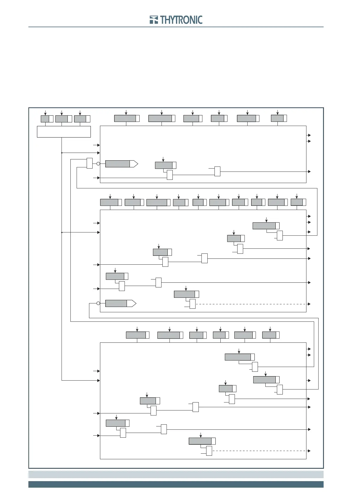
all-F46N.ai
General logic diagram of the unbalance current elements - 46N
≥
IN>AL inhibition
I
N
I
N
I
C
I
C
I
N
IN>AL Element
Start IN>
AL
Trip IN>
AL
t
>
ALdef
INCLP>
ALdef
IN>
ALdef
INCLP>
AL
Mode
tNCLP>
AL
IN>
AL
Enable
Block1
BLK1IN>
AL
&
IN>
AL
BLK1
Start IN>
AL
&
Start IN>
&
IN>
AL
disbyIN>
IN> inhibition
CLPIN>
IN> Element
BLK2OUT
BLK2ININ>
Start IN>
Trip IN>
Block2
&
IN>BLK2IN
IN>BLK2OUT
IN>BF
Trip IN>
&
IN>BF
Start IN>
&
tN
>
def
INCLP>
def
IN>
def
tN
>
inv
INCLP>
inv
IN>
inv
IN>Curve
INCLP>Mode
tNCLP>
IN> Enable
Block1
BLK1IN>
&
IN>BLK1
Start IN>
&
Start IN>
&
Start IN>>
&
IN> disbyIN>>
Start IN>>
&
IN>
AL
disbyIN>>
CLPIN>
IN>> Element
BLK2OUT
BLK2ININ
>
>
Start IN>
>
Trip IN>
>
Block2
&
IN>>BLK2IN
IN>>BLK2OUT
IN>
>
BF
Trip IN
>
>
&
IN>>BF
Start IN
>
>
&
tN
>>
def
INCLP>>
def
IN>>
def
INCLP>>Mode
tNCLP>>
IN>> Enable
Block1
BLK1IN
>
>
&
IN>>BLK1
Start IN
>
>
&
Start IN
>
>
&