57
NC2 0 - Manual - 01 - 2015
FUNCTION CHARACTERISTICS
Phase unbalance current - 46
Preface
The monitoring of fundamental component of the line current unbalance provides a means of detect-
ing changes in impedance resulting from failures and faults within the capacitive, inductive and re-
sistive elements of a capacitor bank / harmonic fi lter circuit. These faults or failures invariably result
in an unbalance in the fundamental frequency component of the line currents.
Two operation thresholds with adjustable operating time with defi nite time characteristic are available.
Operation and settings
The phase unbalance current (fundamental component) is calculated from the fundamental frequen-
cy components of the phase currents.
The unbalance current used for the phase unbalance element is:
I
2
= [max (I
L1
, I
L2
, I
L3
) - min (I
L1
, I
L2
, I
L3
)] / mean (I
L1
, I
L2
, I
L3
)
If the unbalance phase current exceeds the setting thresholds a start is issued. After expiry of the
associated operate time a trip command is issued; if instead the current drops below the threshold,
the element is restored.
The element can be enabled or disabled by setting ON or OFF the the I2> Enable parameter inside
the Set \ Profi le A(or B) \ Phase unbalance-46 \ I2> Element \ Setpoints menu and the State param-
eter inside the Set \ Profi le A(or B) \ Phase unbalance-46 \ I2> Element \ Defi nite time menu.
t-int-F46.ai
I
2
t
2
>
def
t
2
>>
def
I
2
>>
def
I
2
>
def
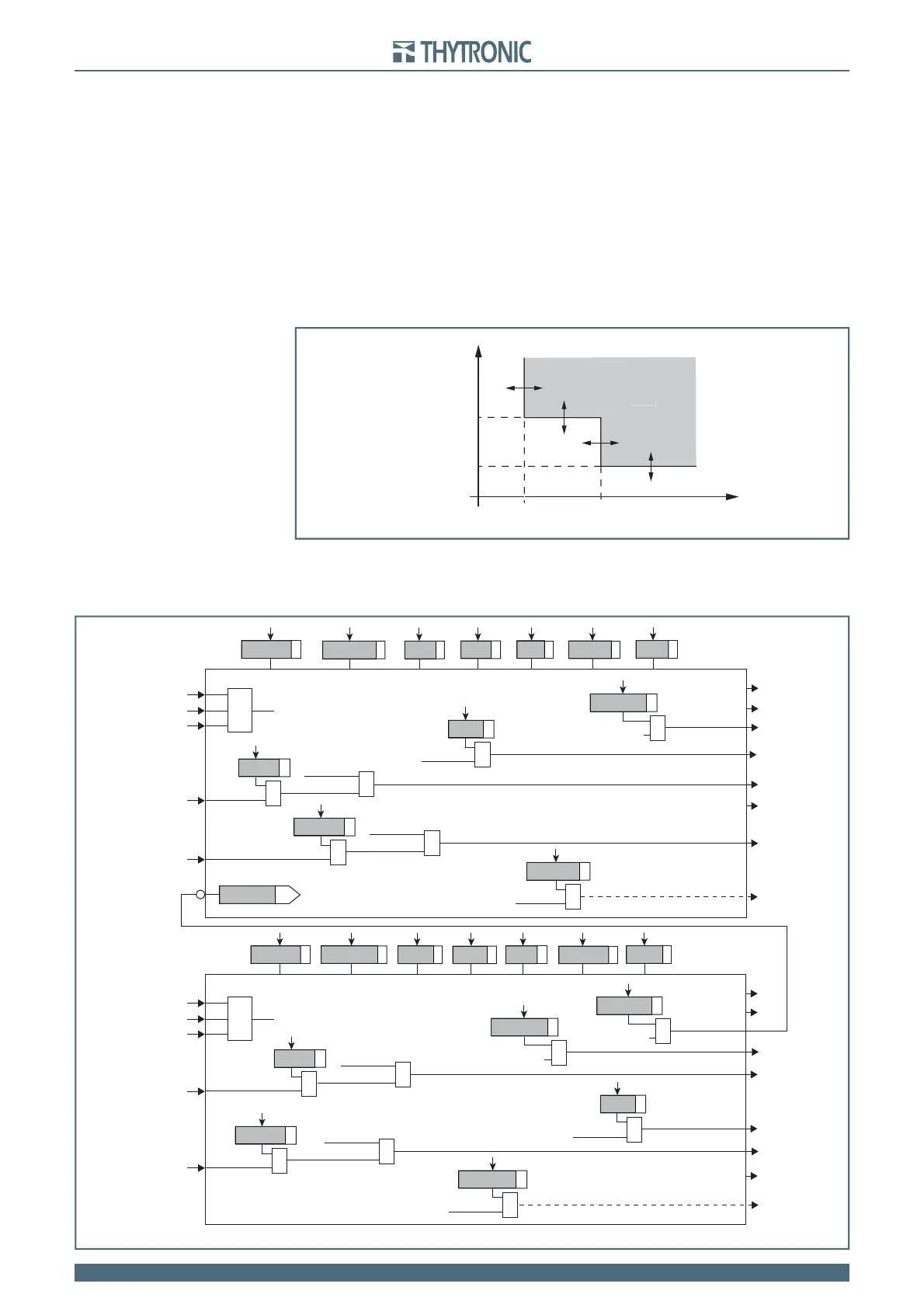
General operation time characteristic for the phase unbalance elements - 46
t
TRIP
t-int-F46.ai
I
2
t
2
>
def
t
2
>>
def
I
2
>>
def
I
2
>
def
General operation time characteristic for the phase unbalance elements - 46
t
TRIP
all-F46.ai
General logic diagram of the phase unbalance element - 46
I
L1
I
L2
I
2
I
L3
I2> inhibition
BLK1I2>>
I2>> Element
Start I2>>
Trip I2>>
Start I2>>
&
I2> disbyI>>
t2
>>
def
ICLP2>>
def
I2>>
def
ICLP2>>Mode
tCLP2>>
t2
>>
RES
I2> Element
Start I2>
Trip I2>
Start I2>
&
I2> disbyI2>>
Start I>>
&
I>AL disbyI>>
t2
>>
def
I2CLP>>
def
I2>
def
I2CLP>Mode
t2CLP>
t
2>
RES
I2> Enable
I2>> Enable
CLPI2>
CLPI2>>
I2>>BF
Trip I>>>
&
I>>>BF
I2>BF
I2> Trip
&
I2>BF
BLK2OUT
I2>BLK2OUT
Start I2>
&
BLK2OUT
I2>>BLK2OUT
Start I2>>
&
BLK1I2>
&
I2>BLK1
Block1
Start I2>
&
&
I2>>BLK1
Block1
Start I2>>
&
&
I2>BLK2IN
BLK2INI2>
Block2
Start I2>
&
&
I2>>BLK2IN
Block2
BLK2INI2>>
Start I2>>
&
I
L1
I
L2
I
2
I
L3