54
54
NC2 0 - Manual - 01 - 2015
FUNCTION CHARACTERISTICS
Undercurrent - 37
Preface
Two operation thresholds, independently adjustable with adjustable delay and defi nite time charac-
teristic.
The fi rst one operates with OR logic, while the second threshold operates with AND logic.
Both thresholds may be temporarily disabled by MMI command.
Each threshold may be separately enabled or disabled.
Operation and settings
The RMS phase currents I
L1RMS
, I
L2RMS
, I
L3RMS
(including up to eleventh harmonic) are compared
with the setting values (I<
def
, I<<
def
).
For the fi rst threshold a start is issued when at least one of the three currents goes down the adjust-
able threshold (OR logic), while, for the second threshold, a start is issued when all the three currents
go down the adjustable threshold (AND logic).
After expiry of the associated operate time (t<
def
, t<<
def
) a trip command is issued; if instead the cur-
rents exceed the threshold, the element is restored.
Each element can be enabled or disabled by setting ON or OFF the State parameter inside the Set
\ Profi le A(or B) \ Undercurrent-37 \ I< (I<< Element) \ Defi nite time
All the named parameters can be set separately for Profi le A and Profi le B (Set \ Profi le A(or B) \
Undercurrent - 37 \ I< Element (I<< Element) \ Setpoints menus).
For every of the two thresholds the logic block can be set.
Logical block (Block1)
If the I<BLK1 and/or I<<BLK1 enabling parameters are set to ON and a binary input is designed
for logical block (Block1), the protection is blocked off whenever the given input is active.
The trip timer is held in reset condition, so the operate time counting starts when the input block
goes down.
[1]
The enabling parameters are available inside the Set \ Profi le A(or B) \ Undercurrent
- 37 \ I< Element (I<< Element) \ Setpoints menus, while the Block1 function must be assigned to the
selected binary input inside the Set \ Inputs \ Binary input IN1(x) menus (IN1 or INx matching).
Note 1 The exhaustive treatment of the logical block (Block 1) function may be found in the “Logic Block” paragraph inside CONTROL AND MONITOR-
ING section.
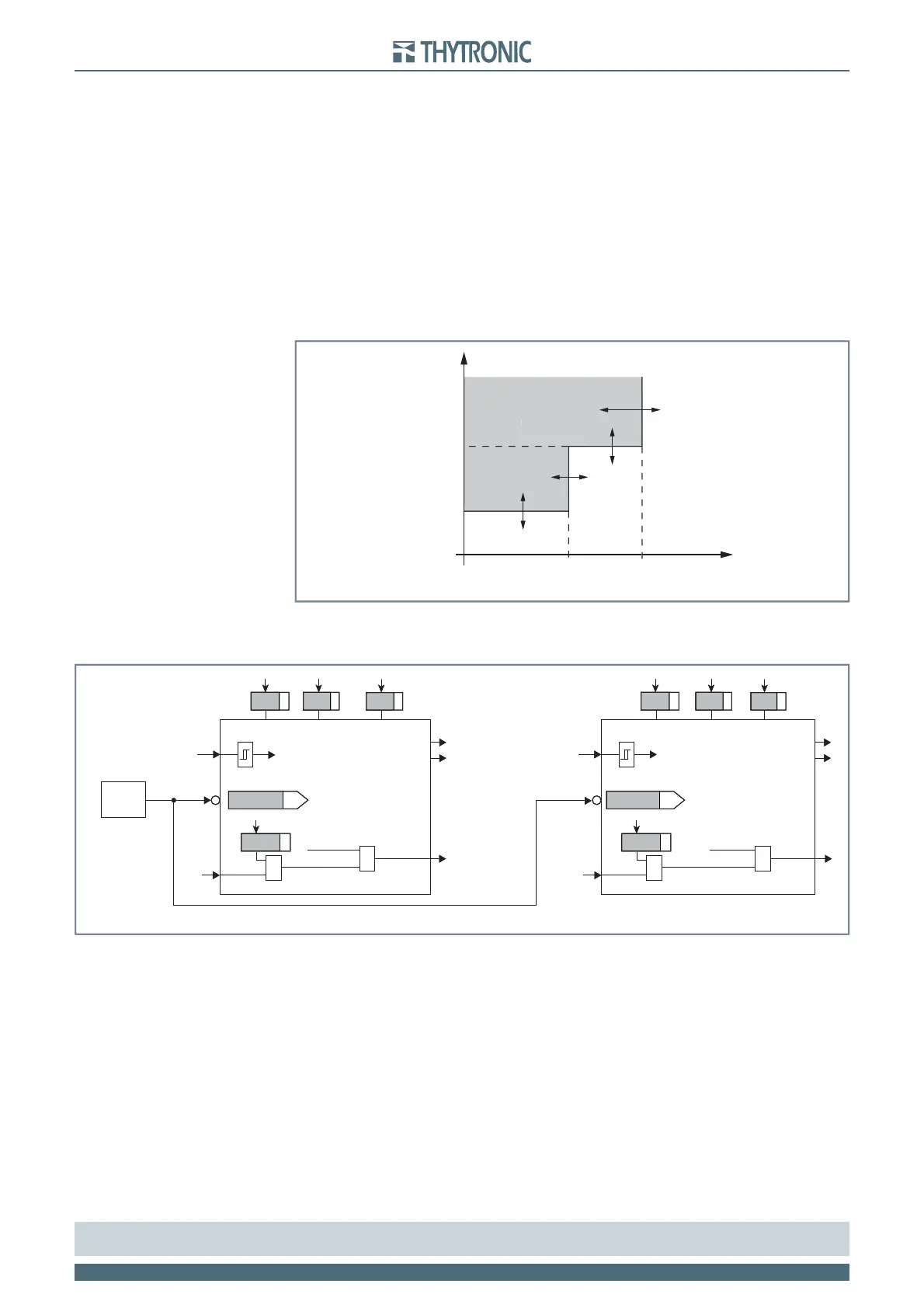
t-int-F37.ai
I
RMS
I<< I<
t<<
t
t<
General operation time characteristic curve for the undercurrent elements - 37
TRIP
t-int-F37.ai
I
RMS
I<< I<
t<<
t
t<
General operation time characteristic curve for the undercurrent elements - 37
TRIP
all-F37.ai
I
L1RMS
, I
L2RMS
, I
L3RMS
I
L1RMS
, I
L2RMS
, I
L3RMS
MMI
I<< Element I< Element
Disable 37 elements
Start I<< Start U<
Trip U<Trip I<<
I< inhibition I<< inhibition
t
<
def
I<
def
t
<<
def
I<<
def
State State
Block1
BLK1I<
&
I<BLK1
Start I<
&
Block1
BLK1I<<
&
I<<BLK1
Start I<<
&
General logic diagram of the undercurrent elements - 37