164
164
NC2 0 - Manual - 01 - 2015
SETTING AND COMMISSIONING
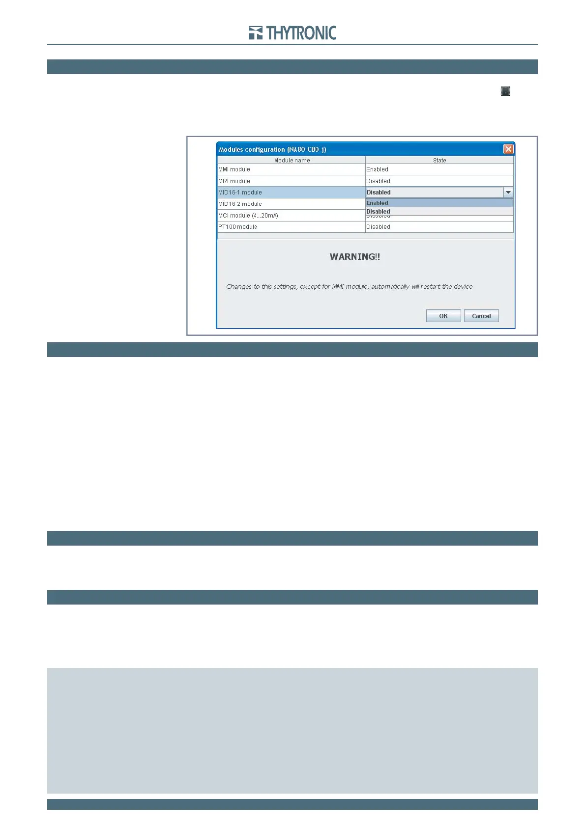
7.4 MODULES MANAGEMENT
After installation, the modules must be enabled (working with level 1 session level).
The Thybus modules may be set inside the Procedure menu (or by means a click on the
icon).
Following up any module confi guration an automatic reset is issued and the I/O devices are included
inside the device menu.
[1]
When two MID16 modules are enabled, the hardware address must be
set; the dip-switch layout is showed inside the INSTALLATION section
7.5 MAINTENANCE
The Pro-N relays do not require any particular maintenance; all circuits use high quality static com-
ponents, the subassembly products undergo dynamic checks on their functioning before the fi nal
assembling of the complete equipment. The dedicated circuits and the fi rmware for the self-test
function continuously check the relay operation; the continuously operating auto-zeroing function
dynamically corrects the measuring errors due to offset, heat dependent drifts, aging of components,
etc.
The microprocessor is equipped with a watch-dog circuit which restores the correct operation of
the fi rmware in case of fault.
The possibility of reading the value of the signals measured on the display (the NA60 relay used as an
ammeter) allows one to check both the system parameters and the operation of the protection relays
at any time. The NA60 relay can be preset as well to show the current values referred to the nominal
current of the current transformers, as directly in primary amperes (according to the preset value of
CT’s nominal primary current); the same is done for the input voltages.
If connected to the central control unit, all data available on the display can be checked and pro-
cessed thus performing a continuous check and maintenance.
7.6 REPAIR
No repair of possible faults by the client is foreseen; if following to any irregularity of operation, the
above tests confi rm the presence of a fault, it will be necessary to send the relay to the factory for
the repair and the consequent settings and checks.
7.7 PACKAGING
The Pro-N devices must be stored within the required temperature limits; the relative humidity should
not cause condensation or formation of frost.
It is recommended that the devices are stored in their packaging; in the case of long storage, espe-
cially in extreme climatic conditions, it is recommended that the device is supplied with power for
some hours before the commissioning, in order to bring the circuits to the rating conditions and to
stabilize the operation of the components.
Note 1 Binary inputs and output names (ThySetter):
Binary inputs for devices with two inputs onboard IN1, IN2 on board
IN3...IN10 with MRI module
IN11...IN26 with one MID16 module
IN27...IN42 with two MID16 modules
Binary inputs for devices with fi ve inputs onboard IN1...IN5 on board
IN6...IN13 with MRI module
IN14...IN29 with one MID16 module
IN30...IN45 with two MID16 modules
Output relays K1...K6 on board
K7...K10 with MRI module
LEDs: ON, START, TRIP, L1...L5 on board
L6...L10 with MRI module