66
66
NC2 0 - Manual - 01 - 2015
FUNCTION CHARACTERISTICS
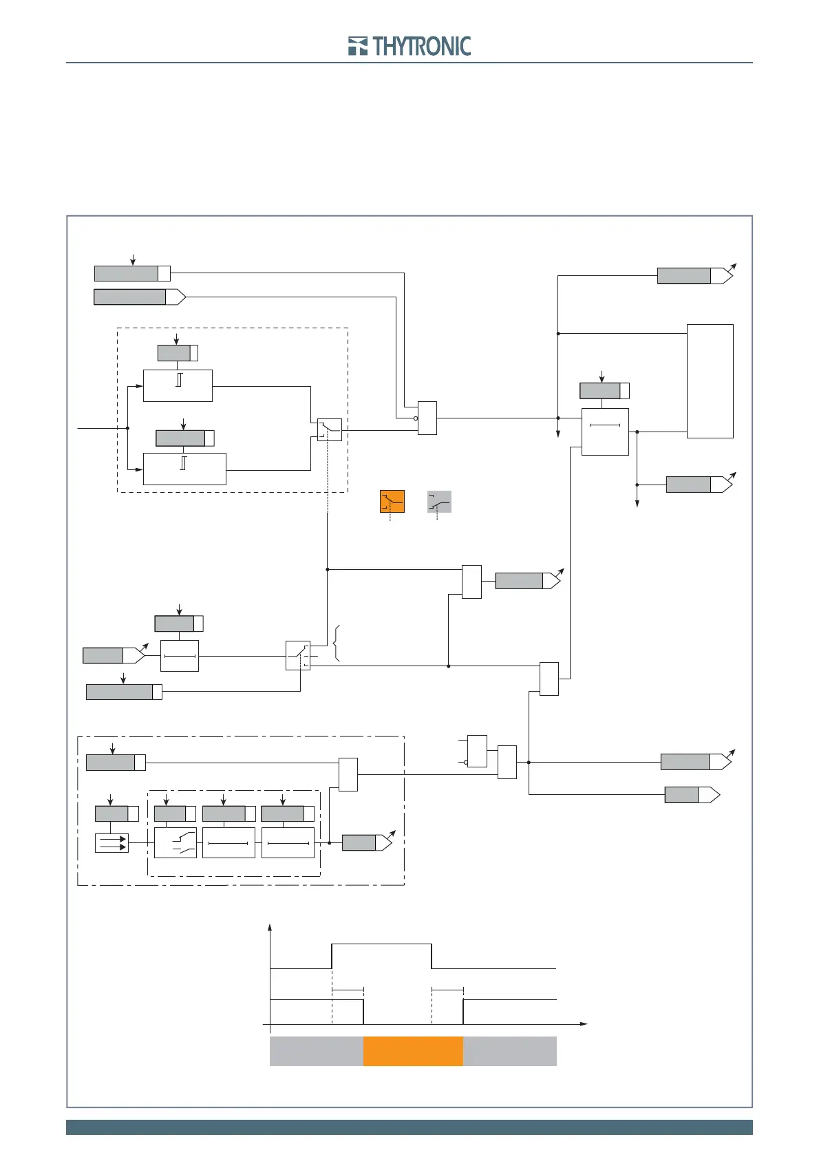
Use of output relay (K1...K6):
If the IN>BLK2OUT enable parameter is set to ON and a output relay is designed for selective
block (Block2), the protection issues a block output by earth elements (BLK2OUT-IE) or by any pro-
tection element (BLK2OUT-Iph/IE), whenever the given element (Start IN>, Start IN>>) becomes ac-
tive. The enable IN>BLK2OUT, IN>>BLK2OUT parameters (ON or OFF) is available inside the
Set \ Profi le A(or B) \ Neutral unbalance current-46N \ Element IN> (Element IN>>) Element \ Set-
points menus, while the BLK2OUT-Iph-K, BLK2OUT-Iph/IE-K and/or BLK2OUT-IE-K output
relays and LEDs (BLK2OUT-Iph-L, BLK2OUT-Iph/IE-L e/o BLK2OUT-IE-L) must be select
inside the Set \ Profi le A(or B) \ Selective block-BLOCK2 \ Selective block OUT menu.
•
46NAL.ai
I
NC
RESET
t
N>ALdef
0T
≥1
Start IN>AL
Trip I>AL
CB-State
ON≡Inhibit (from IN> and/or IN>> element)
ON≡Enable IN>AL unbalance current element
(Pickup within CLP)
(Pickup outside CLP)
IN>AL inhibition
&
T0
t
NCLP>AL
INCLP>ALMode
I
NCLP
>
AL
def
t
NCLP>AL
TRIPPING MATRIX
(LED+RELAYS)
A
B
C
A =“1”A =“0 or OFF”
Output t
NCLP>AL
IN>AL Enable
t
NCLP>
CB State CB OPEN CB CLOSED CB OPEN
Output t
NCLP>
t
0.1 s
HIGH THRESHOLD/
BLOCK
LOW THRESHOLD/
UNBLOCK
HIGH THRESHOLD/
BLOCK
A = ON - Change setting
B = OFF
C = ON - Element blocking
IN>ALTR-K
IN>ALTR-L
IN>ALST-L
IN>ALST-K
≥1
CLP IN>AL
I
NC
≥
I
N
>
ALdef
I
N
>
ALdef
I
NC
≥
I
NCLP
>
AL
def
t
N>ALdef
Neutral unbalance current (46N) - Alarm element logic diagram (IN>
AL
)
Binary input INx
T0
Logic
INx
t
ON
INx
t
ON
INx
t
OFF
T0
n.o.
n.c.
INx
t
OFF
BLK1IN>AL
&
&
&
Enable (ON≡Enable)
IN>ALBLK1
Block1
Start I
N
>
AL
Trip I
N
>
AL
Block1
Block1
Block1