83
NC2 0 - Manual - 01 - 2015
FUNCTION CHARACTERISTICS
Similarly, the operation of I> element may be inhibited by the start of the second and/or third
element (I>>, I>>>) of the fundamental frequency phase overcurrent by setting ON the Dis-
able I> by start I>> and/or I>>> (I>disbyI>>, I>disbyI>>>) parameters available inside the
Set \ Profi le A(or B) \ Phase overcurrent-50/51 Fundamental \I>> Element, I>>> Element \ Setpoints
menus.
All the named parameters can be set separately for Profi le A and Profi le B (Set \ Profi le A(or B)\
Phase overcurrent-50/51 RMS \ I> Element (I>AL Element, I> Element) \ Setpoints menus).
An adjustable reset time delay is provided for the operation threshold (t
>RES
).
The operation threshold element can produce the Breaker Failure output if the I> BF parameter is
set to ON. The parameter is available inside the Set \ Profi le A(or B) \ Phase overcurrent-50/51 RMS
\ I> Element \ Setpoints menu.
[1]
If the CLP function (Cold Load Pick-up) is enabled for element blocking, the selected threshold may
be blocked for an adjustable time interval, starting from the circuit breaker closure.
This operating mode may be select by setting ON-Element blocking the ICLP>AL Mode and/or
ICLP> Mode parameters.
If the CLP function (Cold Load Pick-up) is enabled for threshold change, the selected threshold may
be changed for an adjustable time interval, starting from the circuit breaker closure.
This operating mode may be select by setting ON-Change setting the ICLP>AL Mode and/or
ICLP> Mode parameters, whereas the operating thresholds within the CLP may be adjusted inside
the Set \ Profi le A(or B) \ Phase overcurrent-50/51 RMS \ I>AL Element,(I> Element) \ Defi nite time
(Inverse time) menus.
For both operating modes the CLP Activation time parameters (tCLP-AL, tCLP>) may be adjusted
inside the Set \ Profi le A(or B)\ Phase overcurrent-50/51 RMS \ I>AL Element (I> Element) \ Setpoints
menus.
For every of the two thresholds the following block criteria are available:
Logical block (Block1)
If the I>ALBLK1 and/or I>BLK1 enabling parameters are set to ON and a binary input is designed
for logical block (Block1), the concerning element is blocked off whenever the given input is active.
[2]
The enabling parameters are available inside the Set \ Profi le A(or B) \ Phase overcurrent-50/51 RMS
\ I>AL Element (I> Element) \Setpoints menus, while the Block1 function must be assigned to the
selected binary input inside the Set \ Inputs \ Binary input IN1(x) menus.
Note 1 The common settings concerning the Breaker failure protection are adjustable inside the Breaker Failure - BF menu.
Note 2 The exhaustive treatment of the logical block (Block 1) function may be found in the “Logic Block” paragraph inside CONTROL AND MONITOR-
ING section
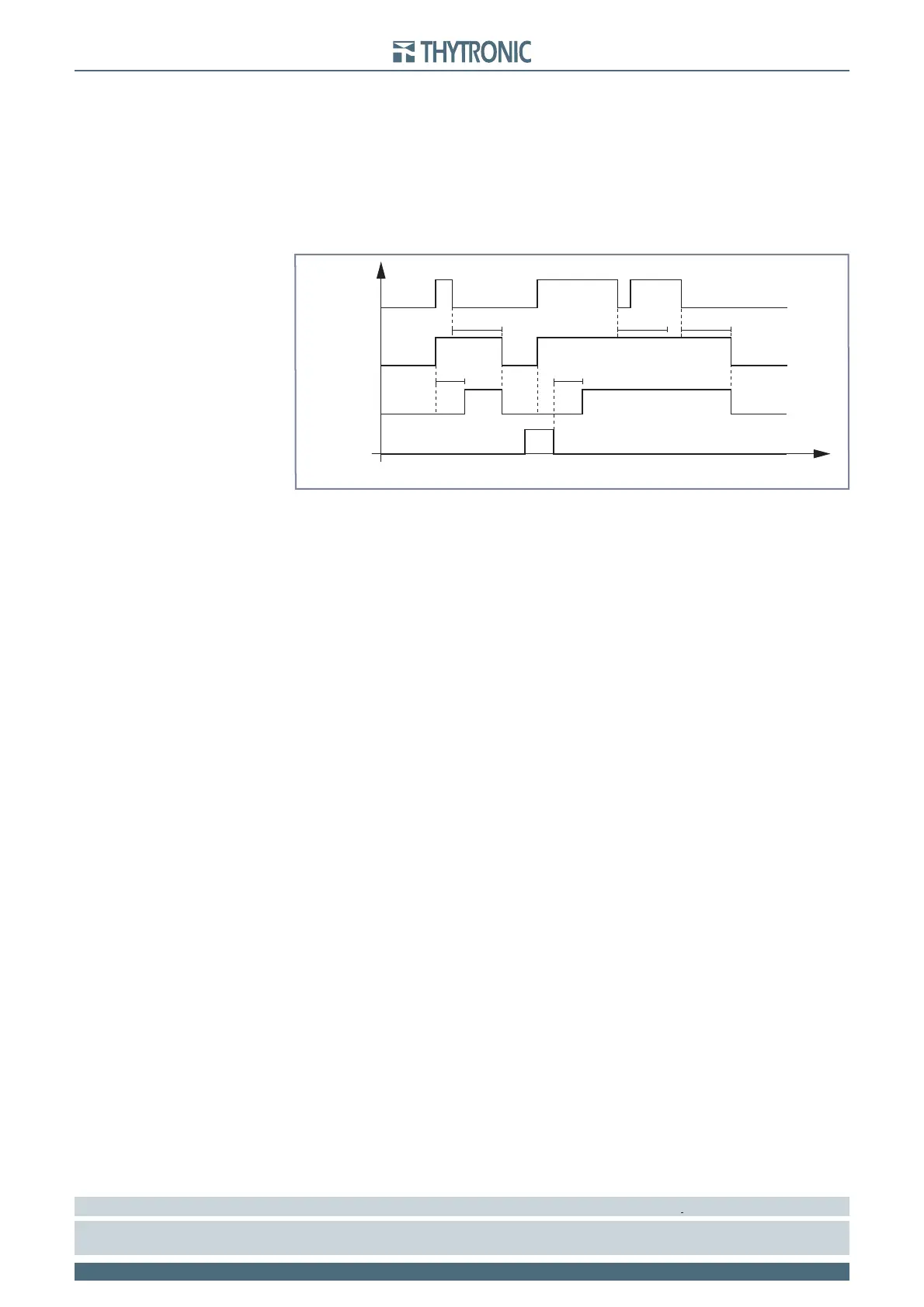
Timers-F50-51.ai
I> Start
I> Trip
t
>
t
>
RESET
INPUT
t
>RES
t
>RES
t
>RES
t
I> element phase overcurrent timers - 50/51