90
90
NC2 0 - Manual - 01 - 2015
FUNCTION CHARACTERISTICS
If the CLP function (Cold Load Pick-up) is enabled for element blocking, the selected threshold may
be blocked for an adjustable time interval, starting from the circuit breaker closure.
This operating mode may be select by setting ON-Element blocking the ICLP>> Mode and/or
ICLP>>> Mode parameters.
If the CLP function (Cold Load Pick-up) is enabled for threshold change, the selected threshold may
be changed for an adjustable time interval, starting from the circuit breaker closure.
This operating mode may be select by setting ON-Change setting the ICLP>> Mode and/or
ICLP>>> Mode parameters, whereas the operating thresholds within the CLP may be adjusted in-
side the Set \ Profi le A(or B) \ Phase overcurrent-50/51 Fundamental \ I>> Element (I>>> Element) \ Def-
inite time menus.
For both operating modes the CLP Activation time parameters (tCLP>>, tCLP>>>) may be ad-
justed inside the Set \ Profi le A(or B) \ Phase overcurrent-50/51 Fundamental \ I>> Element (I>>>
Element) \ Setpoints menus.
For every of the two thresholds the following block criteria are available:
Logical block (Block1)
If the I>>BLK1 and/or I>>>BLK1 enabling parameters are set to ON and a binary input is de-
signed for logical block (Block1), the concerning element is blocked off whenever the given input is
active.
[1]
The enabling parameters are available inside the Set \ Profi le A(or B) \ Phase overcurrent-
50/51 Fundamental \ I>> Element (I>>> Element) \Setpoints menus, while the Block1 function must
be assigned to the selected binary input inside the Set \ Inputs \ Binary input IN1(x) menus.
Note 1 The exhaustive treatment of the logical block (Block 1) function may be found in the “Logic Block” paragraph inside CONTROL AND MONITOR-
ING section
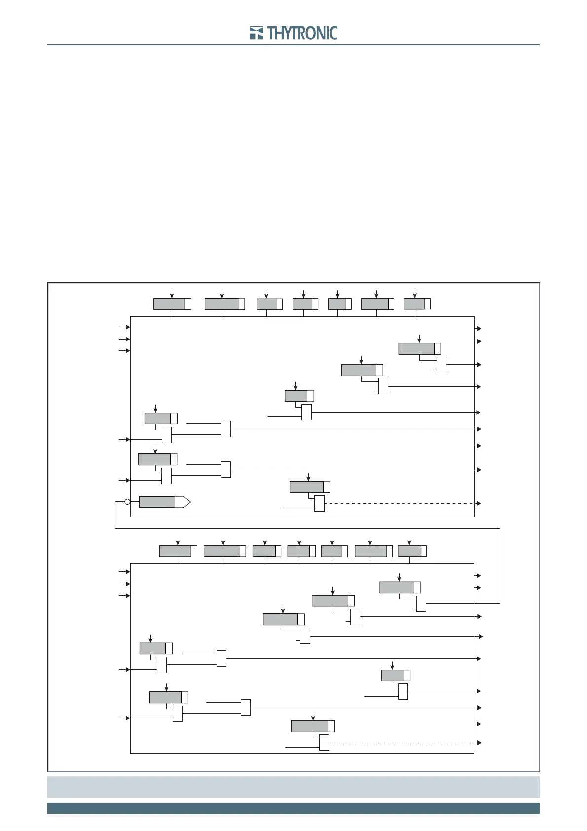
all-F50-51F.ai
General logic diagram of the phase overcurrent elements - 50/51 Fundamental
I
L1
I
L2
I
L3
I
L1
I
L2
I
L3
I>> inhibition
BLK1I>>>
I>>> Element
Start I>>>
towards
50/51RMS
towards
50/51RMS
Start I>>>
Trip I>>>
&
I>> disbyI>>>
Start I>>>
&
I> disbyI>>>
t
>>>
def
ICLP>>>
def
I>>>
def
ICLP>>>Mode
tCLP>>>
t
>>>
RES
I>> Element
Start I>>
Trip I>>
Start I>>
&
I>AL disbyI>>
Start I>>
&
I>AL disbyI>>
t
>>
def
ICLP>>
def
I>>
def
ICLP>>Mode
tCLP>>
t
>>
RES
I>> Enable
I>>> Enable
CLPI>>
CLPI>>>
I>>>BF
Trip I>>>
&
I>>>BF
I>>BF
I>> Trip
&
I>>BF
BLK2OUT
I>>BLK2OUT
Start I>>
&
BLK2OUT
I>>>BLK2OUT
Start I>>>
&
Start I>>
&
I> disbyI>>
BLK1I>>
&
I>>BLK1
Block1
Start I>>
&
&
I>>>BLK1
Block1
Start I>>>
&
&
I>>BLK2IN
BLK2INI>>
Block2
Start I>>
&
&
I>>>BLK2IN
Block2
BLK2INI>>>
Start I>>>
&