16
E
N
G
L
I
S
H
Alpha Black Disassembly Instructions
Set up a workbench with plenty of workspace to make sure no small parts become lost.
Always wear eye protection (like safety glasses) when performing any marker disassembly
or re-assembly. Refer to the Parts Diagram for these instructions (item numbers
are in parentheses). When disassembling the marker, pay close attention to how the parts t
together to make later re-assembly easier and accurate.
1. Follow Unloading Your Marker on page 10 and Air/CO2 Cylinder Removal instructions
on page 14.
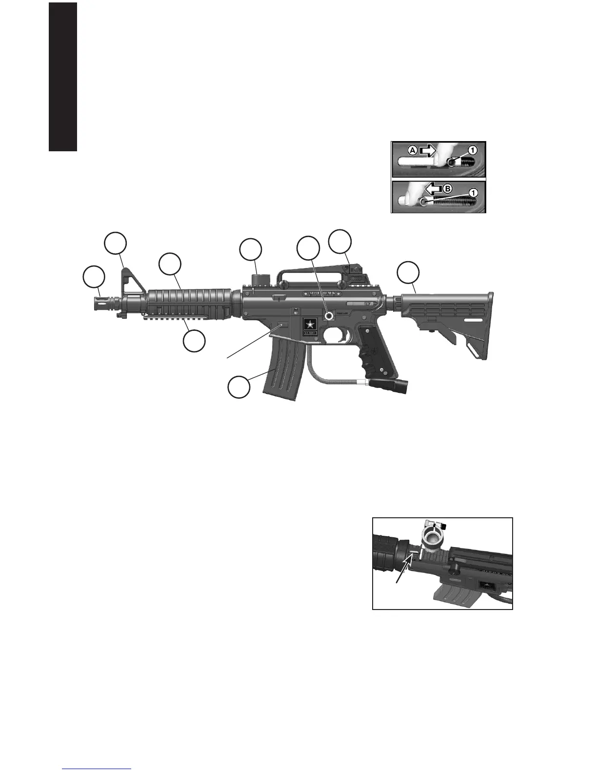
2. Put the marker into the uncocked position. Hold the Rear
Bolt Handle (#1 in Figure 10) with your nger (arrow A).
While holding the handle, pull the trigger and allow the
Rear Bolt Handle to move slowly forward (arrow B in
Figure 10) which uncocks the marker.
3. To remove the Barrel (51), simply turn the Barrel counterclockwise from the Receiver.
To reinstall it, turn it clockwise to thread it into the Receiver. Make sure the O-Ring (15)
is lubricated with Tippmann Certied Marker Oil when re-assembling the barrel to the
marker.
4. To remove the Magazine (55), press two magazine tabs in, and slide the magazine out
the bottom of the marker.
5. Turn the Velocity Screw (4) in until it stops. Loosen
two Air Supply Adapter (ASA) screws (39 and 40).
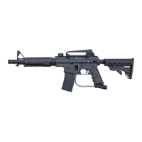
6. To remove the Feed Elbow (41), press down the small
Feed Elbow Latch (33) to unlock it, then tilt the Feed
Elbow out, and slide it off the right side of the Receiver.
7. Remove the Carry Handle Assembly by turning the two
Clamp Nuts (64) counter-clockwise until loose. When
loose, slide the handle off of the Picatinny Rail.
8. Remove screw holding the Collapsible Stock (56) to
the End Cap (19), shown in Figure 2 on page 8. Pull
down on the stock to remove it.
9. To remove the left-side Receiver (36), unscrew six receiver bolts (37 and 38). Then
carefully lift the left-side receiver to access the internal parts.
10. With left half removed (as shown in Figure 15), pull the End Cap (19) out to remove
the Bumper O-Ring (15), Guide Pin (14) and Drive Spring (13). These parts must
be removed before the Rear Bolt Handle (12) can be removed.
Figure 12: Press this latch
to release the Feed Elbow.
Figure 10: Rear Bolt Handle
51
59
62
22
Figure 11: Alpha Black Elite Components
57
56
41
58
55
magazine taB