17
E
N
G
L
I
S
H
11. Disconnect the Linkage
Arm
(16) from the Rear
(9) and Front Bolt (17).
12. Slide the Front Bolt off
the Power Tube (3) and
check the O-Ring (18).
Clean and oil the O-Ring
or if damaged, replace
with a new one. Do the
same with the Rear Bolt
O-Ring (10).
Power Tube and Valve
Refer to the Parts Diagram for these instructions.
NOTE: Do not remove the gas line tting unless it is leaking or you need to replace the valve.
If you do, use teon tape or paste on the tting before reinstalling it. Carefully hand start all
threaded parts and do not overtighten and strip threaded parts when assembling.
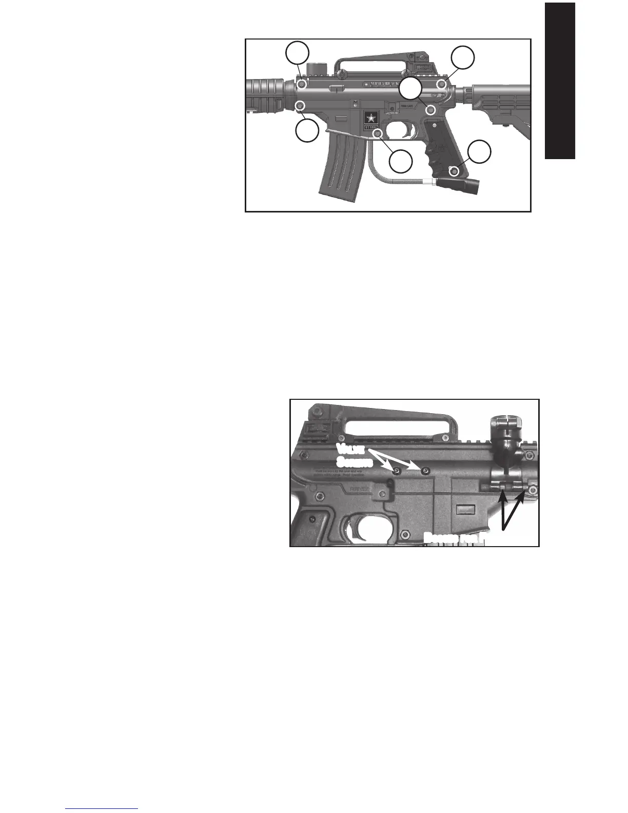
1. To remove the Power Tube and Valve (5), unscrew two Screws (8) from the right side
of the receiver shown in Figure 14.
2. To remove the Valve from the
Power Tube, use a wrench to
slowly unscrew the Gas Line (6)
tting. Once the tting is out, the
Valve will slide out the back of
the power tube.
NOTE: Check the external Valve
O-Ring (A) and if damaged, replace
with a new one. If the O-Ring is
damaged your marker will not function
correctly.
Clean all parts and oil the O-Rings.
3. Reinstall the Valve into the Power
Tube. Insert the cleaned and oiled Valve into the Power Tube and align the holes of
the Valve and Power Tube. Apply teon tape or thread paste on threads of Gas Line
tting and carefully screw it into the Valve. Snug with a wrench (do not over tighten and
possibly strip threaded parts). Wipe off any excess thread paste if used.
4. Reinstall the power tube/valve into receiver by aligning the holes of the Power Tube and
the right Receiver Half. Apply red loctite #271 sealant to threads of two valve screws
(8) and attach. Do not over tighten bolts and possibly strip threads. Wipe off any excess
loctite.
Figure 13: Remove Screws From Left Receiver Half
38
37
37
37
38
38
Figure 14: Valve Screws and Feed Elbow
BoSSeS for feed eLBow
vaLve
SCrewS