19
E
N
G
L
I
S
H
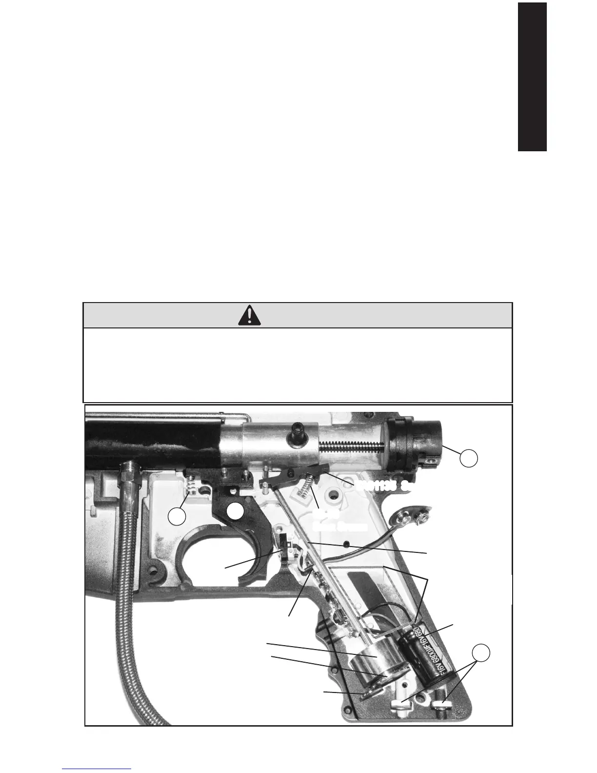
E-Trigger Assembly
Do not operate the electronics assembly uninstalled, as the solenoid/armature may pinch you.
Double check that the E-Trigger parts are positioned correctly for reassembly as shown in
Figure 16 at the bottom of this page.
1. Place Solenoid/Armature (armature ts inside the solenoid) into right receiver.
2. Carefully align and insert the Electronics Assembly into slot.
3. Place Trigger Switch on two pins of right receiver half.
4. Insert Capacitor in slot.
5. Route wires in cutout areas to lay at under armature pin and battery and not be
pinched when receiver halves are reassembled. Visually inspect internal wires for
disconnected wire end(s) or damage.
6. Insert armature pin into 2 slots so it moves freely.
7. Insert Magnet in slot below armature as shown.
8. Double check that all parts are in place as shown.
9. Place battery connector through left receiver half. Make sure the magnet ts into left
receiver half slot so it does not break and wires are not pinched as you place left half on
right half so the halves t ush.
Markers with E-Trigger now go to step 2 on page 18.
WARNING
To prevent a re or shock hazard, do not immerse the electronics
assembly in liquids, and do not disassemble the electronics. The
disposal of the battery used to power this product may be regulated
in your area. Please conform to all State and Local Regulations with
regard to battery disposal.
27
25
35
19
ta05014 magnet
SoLenoid
a
rmature
ta09935
eLeCtroniCS aSSemBLy
ta06020
armature Pin
ta01135 Sear
02-88
Sear SPring
trigger
S
witCh
Battery
C
onneCtor
CaPaCitor
reCeSSed area
for Battery
Figure 16: Reassemble E-Trigger Components