18
E
N
G
L
I
S
H
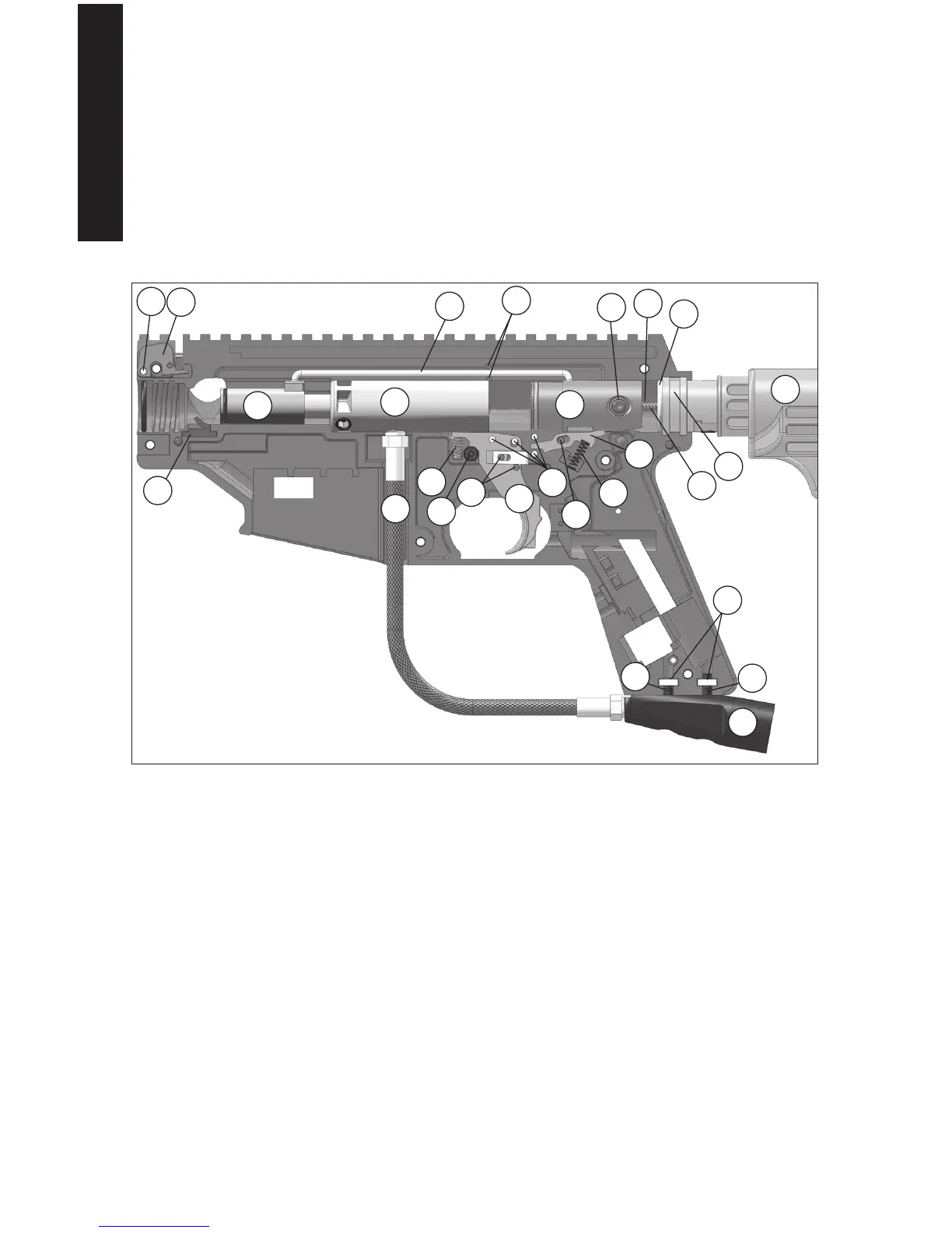
Reassembling Receiver Halves
1. Refer to the Figure 15 and double check that the following parts are in place:
Trigger Assembly and Pins (20, 25, 26, and 27), Safety (22), Sear Pin (21), Sear (29),
Sear Spring (30), Feed Elbow Latch (33), Pin (31), Spring (32, not shown), Front Bolt*
(17), Ball Latch (34), Linkage Arm* (16), Linkage Arm Pins (65, qty 2), Rear Bolt* (9),
Drive Spring* (13), Guide Pin* (14), Bumper O-ring (15), End Cap (19), and two Air
Supply Adapter Nuts (35)
(* = indicates to be lubricated with Tippmann Certied Marker Oil).
For markers equipped with E-Trigger, perform the E-Trigger Assembly on page 19 before
continuing with step 2 below. Markers without E-Trigger, continue with step 2 below.
2. Carefully install the left receiver half (make sure halves t ush).
3. Insert ve of the six Receiver Screws shown in Figure 13. Leave the bottom left #38 (as
shown in Figure 13) out.
4. Reinstall the Barrel Shroud and secure with the remaining Receiver Screw (38) from step 3.
5. Attach the ASA (7), tighten two screws (39 and 40) (NOTE: #39 is the shorter adapter
screw and goes in the front location as shown).
6. Apply marker oil onto the barrel O-Ring, insert the Barrel (9) and carefully screw it in.
7. Slide the Feed Elbow (41) into the Receiver and tilt up until the Feed Elbow Latch (33)
holds it in place.
8. Press in the 2 magazine tabs and slide the magazine (55) up into the marker until the
tabs lock it in place.
NOTE: The magazine may be used to store tools and Tippmann Certied Marker Oil for your
marker.
34
17
3
6
31
16
9
56
27
25
29
30
20
26
21
7
13
35
39
40
Figure 15: Reassemble Internal Components
33
15
22
65
19
12
14