14 Performance Series 450e
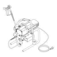
Servicing Repairs at the unit
10. Servicing
10.1 General servicing
Servicing of the unit should be carried out once annually by the
TITAN service.
1. Check high-pressure hoses, device connecting line and
plug for damage.
2. Checktheinletvalve,outletvalveandlterforwear.
10.2 High-pressure hose
Inspect the high-pressure hose visually for any notches or
bulges,inparticularatthetransitioninthettings.Itmustbe
possible to turn the union nuts freely.
11. Repairs at the unit
Switch the unit OFF.
Before all repair work: Unplug the power plug
from the outlet.
11.1 Relief valve
1. Useadriftpunchof2mmtoremovethegroovedpin(Fig.
8,Item1)fromthereliefvalvehandle(2).
2. Removethereliefvalvehandle(2)andcambase(3).
3. Usingawrench,removethevalvehousing(4)fromthe
pumpmanifold(6).
4. Ensurethattheseal(5)isseatedcorrectly,thenscrewthe
newvalvehousing(4)completelyintothepumpmanifold
(6).Tightensecurelywithawrench.
5. Alignthecambase(3)withtheholeinthepumpmanifold
(6).Lubricatethecambasewithgreaseandslideonthe
cam base.
6. Bringtheholeinthevalveshaft(7)andinthereliefvalve
handle(2)intoalignment.
7. Insertthegroovedpin(1)tosecurethereliefvalvehandle
in position.
11.2 Inlet and outlet valve
1. Remove the four screws in the front cover and then
remove the front cover.
2. SwitchtheunitONandthenOFFsothatthepistonrodis
positioned in the lower stroke position.
Danger of crushing - do not reach with the
ngers or tool between the moving parts.
3. Unplugthepowerplugfromtheoutlet.
4. Remove the retaining clip from the connecting bend at the
suction hose and pull off the suction hose.
5. Screw off the return hose.
6. Swiveltheunit90°totherearinordertoworkmoreeasily
on the material feed pump.
7. Unscrewtheinletvalvehousing(Fig.9,Item1)fromthe
pump manifold.
8. Removethelowerseal(2),lowerballguide(3),inletvalve
ball(4),inletvalveseat(5)andO-ring(6).
9. Clean all the parts with the corresponding cleaning agent.
Checktheinletvalvehousing(1),inletvalveseat(5)
andinletvalveball(4)forwearandreplacethepartsif
necessary.Iftheworninletvalveseat(5)isunusedon
one side, install it the other way round.
10. Unscrewoutletvalvehousing(Fig.10,Item7)fromthe
piston(8)withadjustingwrench.
11. Removetheupperballguide(10),crushwasher(9),outlet
valveball(11),andoutletvalveseat(12).
12. Clean all the parts with the corresponding cleaning agent.
Checkoutletvalvehousing(7),outletvalveseat(12),
outletvalveball(11)andupperballguide(10)forwear
and replace parts if necessary. If the worn outlet valve
seat(12)isunusedononeside,installittheotherway
round.
13. Carry out installation in the reverse order. Lubricate O-ring
(Fig.9,Item6)withmachinegreaseandensureproper
seatingintheinletvalvehousing(Fig.9,Item1).
 Loading...