16 Performance Series 450e
Repairs at the unit
15. Guidepiston(3)throughthelowerpackings(9)intothe
pumpmanifold(2)frombelow.Usingarubbermallet,
lightlytapthepiston(3)frombelowuntilitcanbeseen
above the pump manifold.
16. Removeinstallationtoolfrompiston(3).
17. Carefullytightenretainernut(6)withadjustingwrench.
18. Slidethetopofthepiston(3)intotheT-slot(10)onthe
sliderassembly(4).
19. Positionthepumpmanifold(2)underneaththegearunit
housing and push up until it rests against the gear unit
housing.
20. Attachpumpmanifold(2)tothegearunithousing.Ensure
that the pressure sensor does not damage the pressure
sensorseal(10).
21. Screwpumpmanifold(2)tightlytogearunithousing.
22. LubricateO-ring(Fig.9,Item6)betweenpumpmanifold
(2)andinletvalvehousingwithmachinegrease.Screw
inlet valve housing to the pump manifold.
23. Push connection bend of suction hose into the inlet valve
housing(Fig.9,Item1)andsecurewithretainingclip.
Screw on return hose and clamp to suction hose.
24. Install front cover.
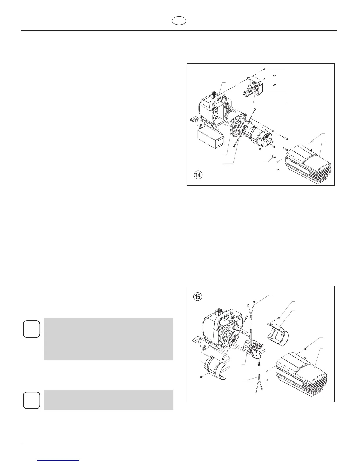
11.4 Replacing the motor assembly
1. Openthereliefvalve,valvepositionPRIME(k
circulation),switchtheunitOFF,andunplugthepower
cord.
2. Removethefourmotorcoverscrews(Fig.14,Item1).
Removethemotorcover(2).
3. Removethefourheatsinkassemblyscrews(3).Pullthe
heatsinkassembly(4)awayfromthegearboxhousing
(5).
4. Disconnectthevewiresfromtherelay(6)thatis
mounted on the inside of the heat sink assembly.
5. Connectthevewirestothenewrelay(refertothe
electricalschematicinsection11.8ofthismanual).
6. Usingthefourheatsinkassemblyscrews(3),installthe
heatsinkassembly(4)ontothegearboxhousing(5).
Tighten the screws securely.
7. Disconnect the black and red wires coming from the gear
box housing. Disconnect the black and red wires from the
capacitors(8).Disconnecttheblackandredwiresfrom
themotor(9).
8. Loosenandremovethefourmotormountingscrews(10).
9. Pull the motor out of the gear box housing.
If the motor will not dislodge from the pump
housing:
• Remove the front cover plate.
• Using a rubber mallet, carefully tap on the
front of the motor crankshaft that extends
through the slider assembly.
10. With the motor removed, inspect the gears in the gear
box housing for damage or excessive wear. Replace the
gears, if necessary.
11. Install the new motor into the gear box housing.
Rotate the motor fan manually until the armature
gear engages with the mating gear in the gear
box housing.
12. Securethemotor(9)withthefourmotormountingscrews
(10).
13. Pushthenewcapacitorsintotheirclip(8)onthenew
motor.
14. Reconnectthewires(refertotheelectricalschematicin
thesection11.8ofthismanual).
15. Slidethemotorcover(2)overthemotor.Securethe
motorcoverwiththefourmotorcoverscrews(1).
11.5 Carbon brushes in motor (Motor Brush kit
P/N 704-276)
1. Removethefourscrews(Fig.15,Item1)atthemotor
cover(2).Removemotorcover.
2. Removethetwoscrews(3)attheshells(4).Remove
shells.
3. Liftupbothcovers(5)withasmallscrewdriver.
4. Pullredwire(6)andblackwire(7)outoftherespective
carbon brush.
5. Insertnewcarbonbrushandsnapcover(5)intoplace.
6. Insertredwire(6)andblackwire(7)ontotherespective
carbon brush.
7. Screwdownbothshells(4).
8. Pushmotorcover(2)overthemotorandfastenwiththe
fourscrews(1).
 Loading...