TM 9-1829A, April 1944 10/100 2021-07-07
Figure 6: Phantom view of speedometer
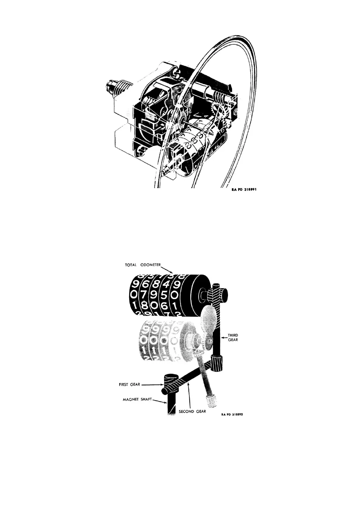
(2) Odometer operation.
a) Total odometer (fig. 7): The total odometer is driven through a series of gears originating at a spiral
gear cut on the magnet shaft. This gear, known as the “first gear,” drives an intermediate “second
gear” and “third gear” which is connected to a “fourth gear” at the odometer. The “fourth gear” turns
the odometer through a series of “star pinion” gears inside the odometer dials or figure wheels. The
total odometer usually has five figure wheels or dials and is so constructed and geared that as any
one wheel finishes a complete revolution it turns the next figure wheel to the left
1
/
10
of a revolution.
Figure 7: Schematic view of total odometer