TM 9-1829A, April 1944 92/100 2021-07-07
60. Assembly
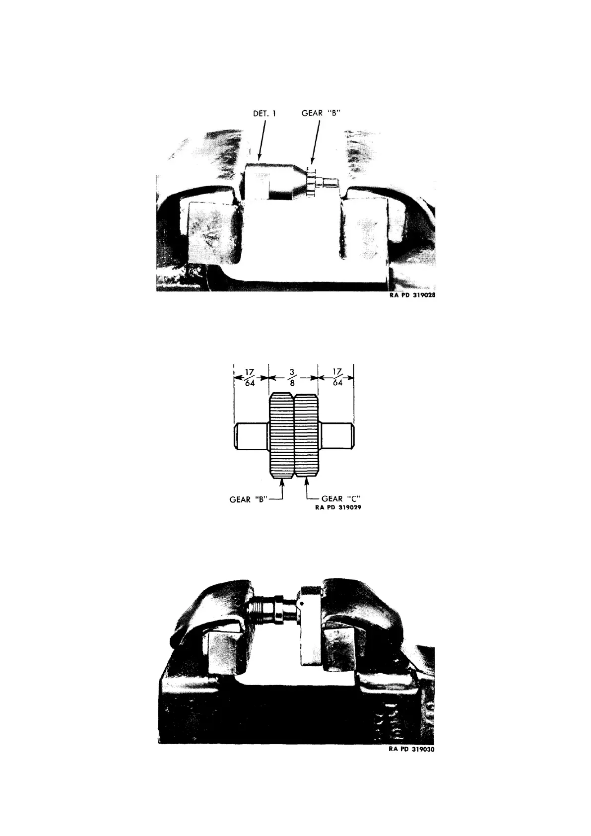
a. Replace intermediate gears (B and C) on shaft: Place special tool (T-178708 Det. 1), new intermediate
shaft, and gear (C) in vise, and press gear (C) about
1
/
4
inch on shaft (fig. 143).
Figure 143: Pressing gear (C), on shaft, using adapter tool (T-178708 Det. 1)
Reverse position of intermediate shaft and press gear (B) on opposite end of shaft until it is flush against gear
(C) (fig. 142). The two gears should now be centered on the shaft so that dimensions are as shown in figure
144.
Figure 144: Dimensional drawing of intermediate gears assembled on shaft
b. Replace sleeve (shaft end): Place shaft side of case and sleeve (with male thread) in vise and press in sleeve
(fig. 145), making sure that slot in sleeve lines up with pin hole in case, using small hammer to drive pin in
place.
Figure 145: Pressing sleeve into case