TM 9-1829A, April 1944 81/100 2021-07-07
46. Operation
a. The recorder is usually installed near the power take-off and is connected to take-off by means of a flexible
shaft. As the inner core of the shaft revolves, it turns the recorder drive gear. The drive gear turns the driven
gear, which turns the odometer gear. This gear turns the odometer through a series of “star pinion” gears
inside the odometer dials or figure wheels. As any one wheel finishes a complete revolution, it turns the next
figure wheel to the left
1
/
10
of a revolution.
47. Disassembly
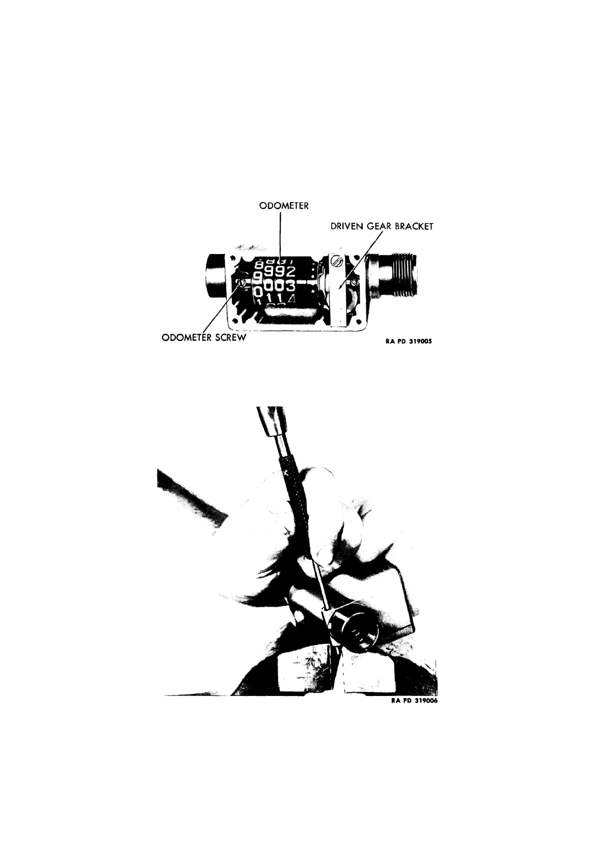
a. Remove odometer and driven gear (fig. 120): Remove four cover screws and lift off cover, window, and
gasket. Remove driven gear bracket screw and lift off bracket and small washer on upper end of driven gear.
Figure 120: Recorder with cover removed
Remove two screws and lift out odometer assembly and driven gear.
b. Remove sleeves and drive gear: Using punch (T-170742), drive out two sleeve retaining pins (fig. 121).
Figure 121: Removing sleeve retaining pin