TM 9-1829A, April 1944 91/100 2021-07-07
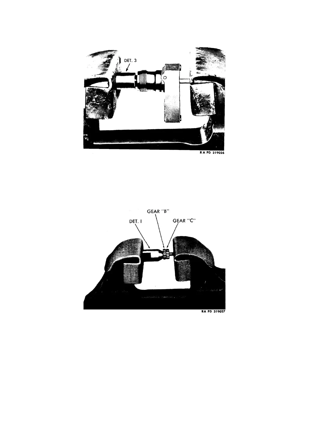
d. Remove gear (D): Place special tool (T-178708 Det 3) and flexible shaft end (has male connection) of drive
joint in vise and press off gear (D) (fig. 141). Lift out driven shaft, gear, and washers.
Figure 141: Removing gear (D), using adapter tool (T-178708 Det. 3)
e. Remove sleeve (shaft end): Place assembly on vise and, using punch (T-170742), drive out pin which holds
sleeve in position (fig. 139). Then drive sleeve out of case (fig. 140).
f. Remove intermediate gears (B and C) from shaft: Do not disassemble intermediate gear assembly unless
gears are worn or defective. If taken apart, a new intermediate gear shaft must be used when the parts are
assembled. Place special tool (T-178708 Det. 1) and intermediate gear assembly in vise, and press. gears off
shaft (fig. 142).
Figure 142: Pressing gears off shaft, using adapter tool (T-178708 Det. 1)
59. Cleaning and inspection
a. Thoroughly clean all parts with brush (T-170755) and dry-cleaning solvent. Dry parts with compressed air.
Examine each one carefully and replace any that are excessively worn, broken or defective. If gears are
defective and part number cannot be identified on old gear, refer to gear ratio chart in parts catalog for part
numbers of proper gears for drive joint being repaired (ratio is stamped on case; fig. 136).