Do you have a question about the Topcon CV-5000 and is the answer not in the manual?
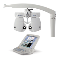
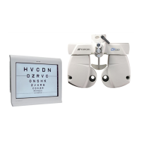
Describes the instrument's function in measuring eye refraction and binocular tests.
Explains how lenses are changed via disks for measurement.
Lists technical specs for power, axis, prism, and pupillary distance.
Details additional specs like adjustment, illumination, and dimensions.
Identifies experienced service engineers as the target audience.
Provides a flowchart for inspection, adjustment, and repair guidance.
Outlines critical safety precautions for component replacement and assembly.
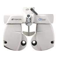
Identifies and explains the function of instrument parts using a diagram.
Details the configuration and purpose of optical components.
Presents a schematic of electrical connections between system components.
Covers step-by-step removal of external and internal components.
Identifies connectors and components on the MAIN, L, and R PCBs.
Explains DIP switch settings for clearing data and zero detection.
Illustrates and names motors and sensors within lens units.
Offers a flowchart for diagnosing and resolving instrument issues.
Guides on installing and calibrating units like spherical and PD.
Details the process for updating the instrument's ROM software using a PC.
Lists and illustrates special tools required for repair and inspection, with their usage.
Lists general tools that may be needed for repair and maintenance tasks.
| Display | Color LCD |
|---|---|
| Astigmatism Axis | 0° to 180° |
| Cross Cylinder | ±0.25D, ±0.50D |
| Rotary Prism | 0 to 20Δ |
| Power Supply | 100-240V AC, 50/60Hz |