− 8 −
3. REPAIR
3-1 Disassembly and Assembly Procedures
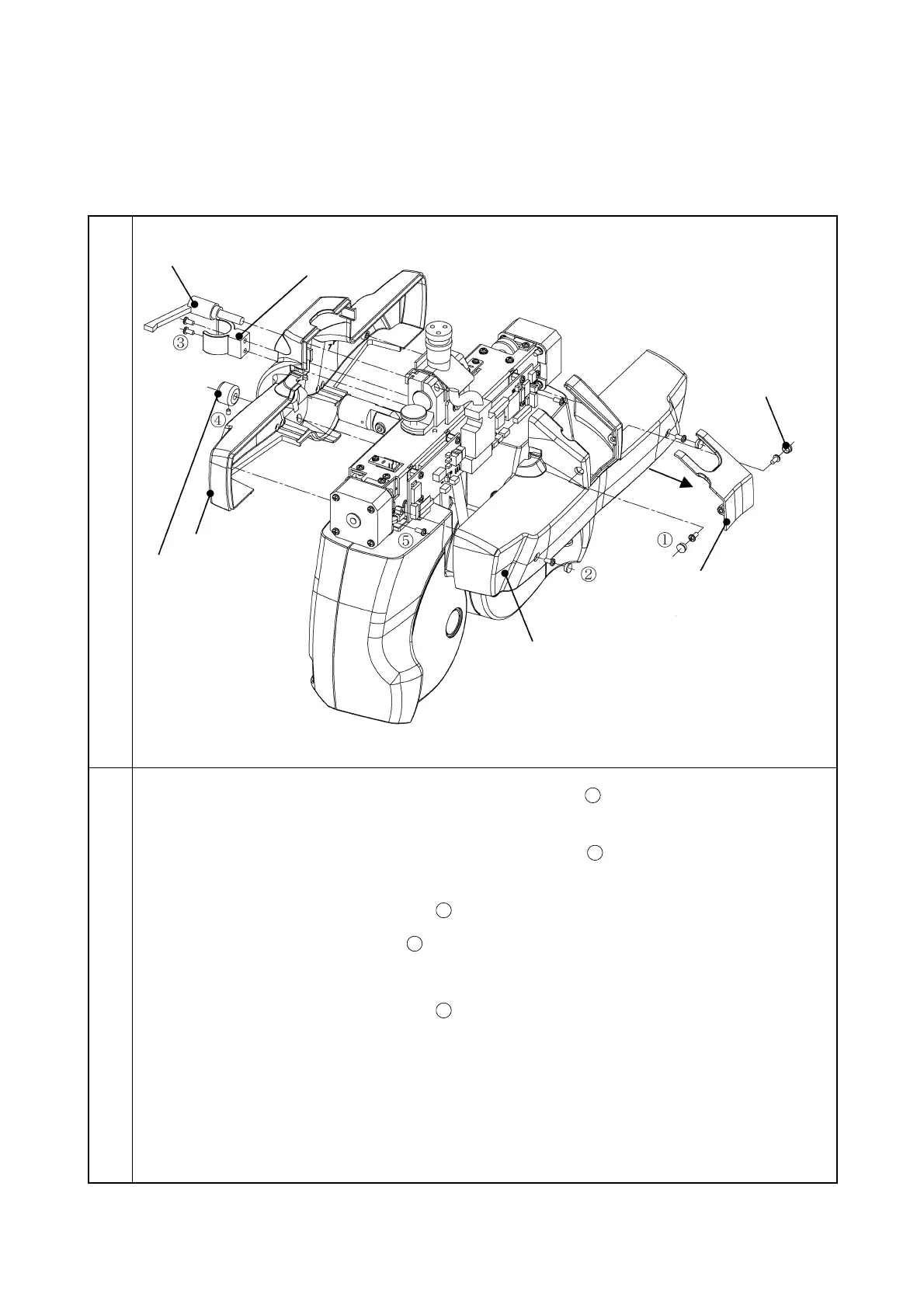
3-1-1 Removal of PD cover
Illustration
Procedure
1. Remove the screw covers and the two screws CR3 × 6SCr
. Then, remove the connector
cover.
2. Remove the screw covers and the two screws CR3 × 6SCr
. Then, remove the PD cover
at inspector side.
3. Remove the two screws CR3 × 6SCr
and then remove the near-point rod holder.
4. Remove the screw 6SU3 × 3SCr
and then remove the forehead rest knob.
5. Remove the tilt fixing lever.
6. Remove the two screws CR3 × 6SCr
and then remove the PD cover at patient side.
Note: When installing the PD connector cover, put the cable into the cover’s groove.
PD cover at inspector side