− 18 −
3-3 Specifications of Switches
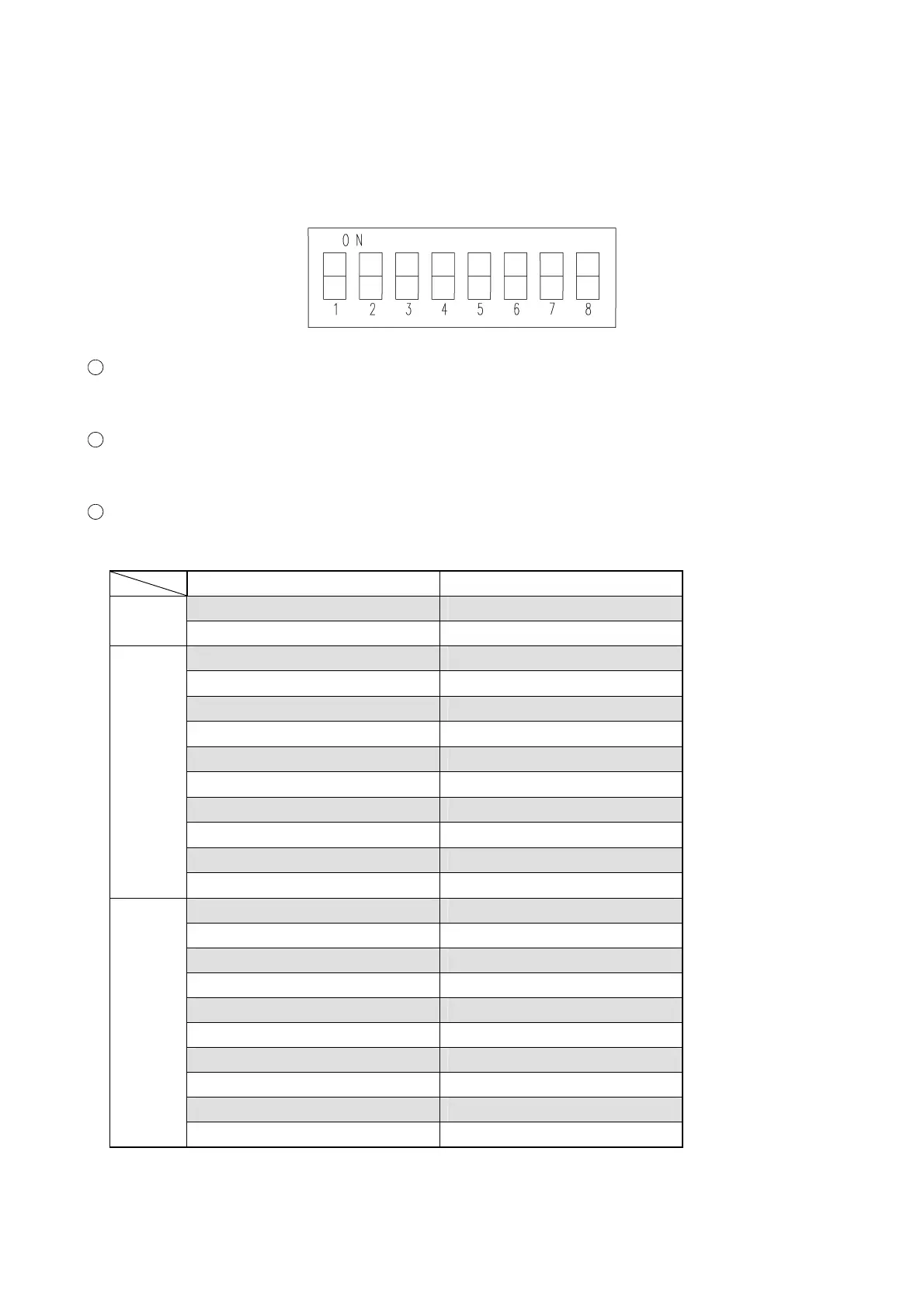
3-3-1 MAIN PCB·SW2
It is necessary to set this DIP SW when correcting the zero detection of each lens.
When clearing all the data of EEPROM
Set No. 7 and No. 8 to “ON”. (Turn on the power, and the data are cleared.)
When clearing part of the EEPROM data (concerned with axis)
Set No. 8 to “ON”. (Turn on the power, and the data are cleared and then zero detection is done.)
When correcting the zero detection of each motor
Set the DIP SW of the lens to be corrected to “ON” to perform correction.
Motor name DIP SW
• PD motor tool mode SW1 is ON.
PD
• Convergence motor tool mode SW2 is ON.
• S1 motor tool mode SW3 is ON.
• S2 motor tool mode SW5 is ON.
• S3 motor tool mode SW1 and SW2 are ON.
• C1 motor tool mode SW1 and SW4 are ON.
• C2 motor tool mode SW1 and SW6 are ON.
• AX motor tool mode SW2 and SW4 are ON.
• RPCC motor tool mode SW2 and SW6 are ON.
• RP1 motor tool mode SW3 and SW5 are ON.
• RP2 motor tool mode SW4 and SW5 are ON.
Right
• CA motor tool mode SW5 and SW6 are ON.
• S1 motor tool mode SW4 is ON.
• S2 motor tool mode SW6 is ON.
• S3 motor tool mode SW1 and SW3 are ON.
• C1 motor tool mode SW1 and SW5 are ON.
• C2 motor tool mode SW2 and SW3 are ON.
• AX motor tool mode SW2 and SW5 are ON.
• RPCC motor tool mode SW3 and SW4 are ON.
• RP1 motor tool mode SW3 and SW6 are ON.
• RP2 motor tool mode SW4 and SW6 are ON.
Left
• CA motor tool mode SW1, SW2 and SW3 are ON.