− 15 −
3-2 Names of PCB
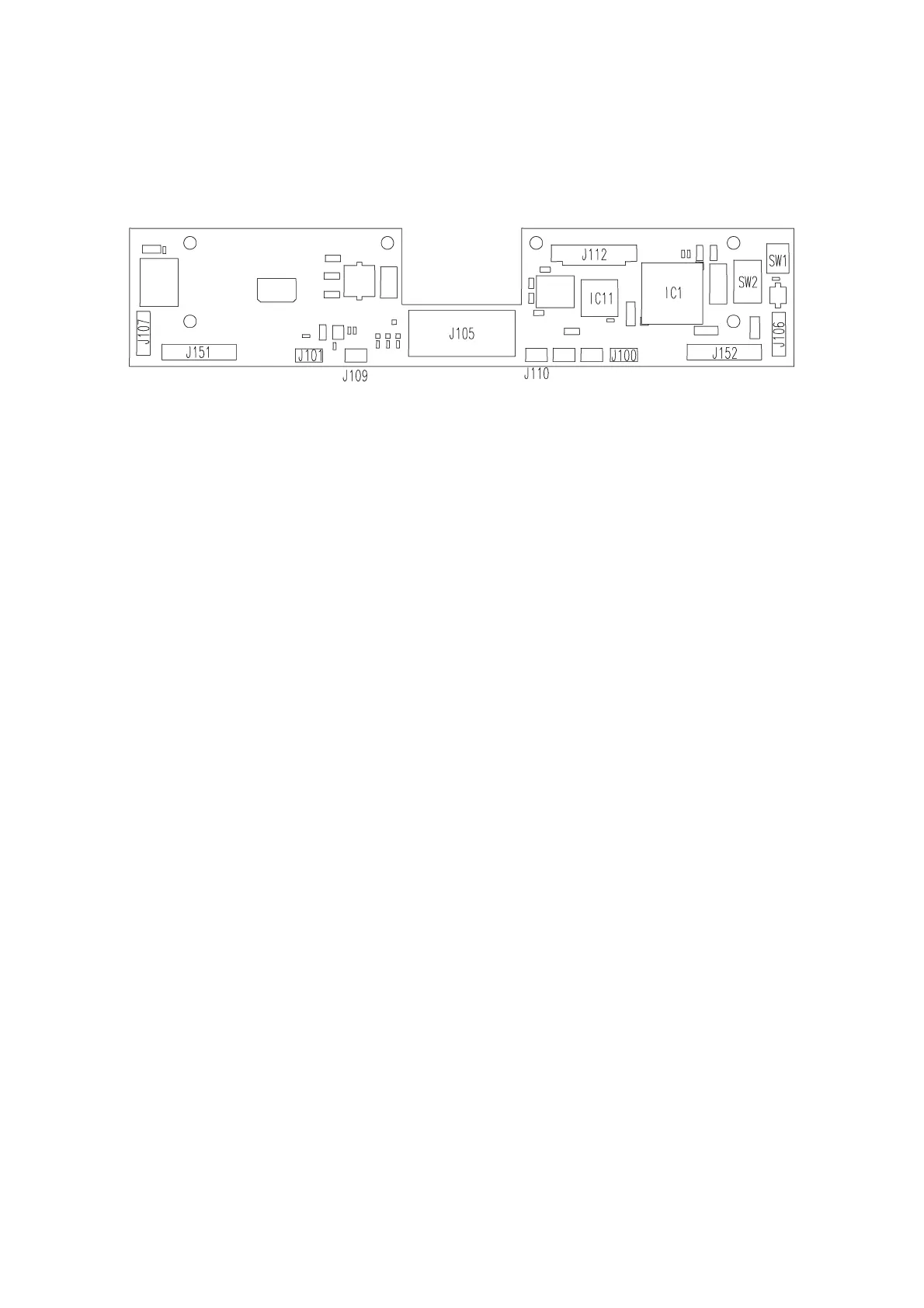
3-2-1 MAIN PCB
J100 : The PD sensor is connected.
J101 : The convergence sensor is connected.
J105 : The power box relay cable is connected.
J106 : The convergence motor is connected.
J107 : The PD motor is connected.
J109 : The near-point chart LED for left eye is connected.
J110 : The near-point chart LED for right eye is connected.
J112 : The tool PCB is connected (when correcting).
J151 : The left eye flexible cable is connected.
J152 : The right eye flexible cable is connected.
SW1 : Zero detection switch
SW2 : DIP switch for correction
IC1 : CPU
IC11 : EEPROM