− 46 −
3-6-4 PD zero position correction
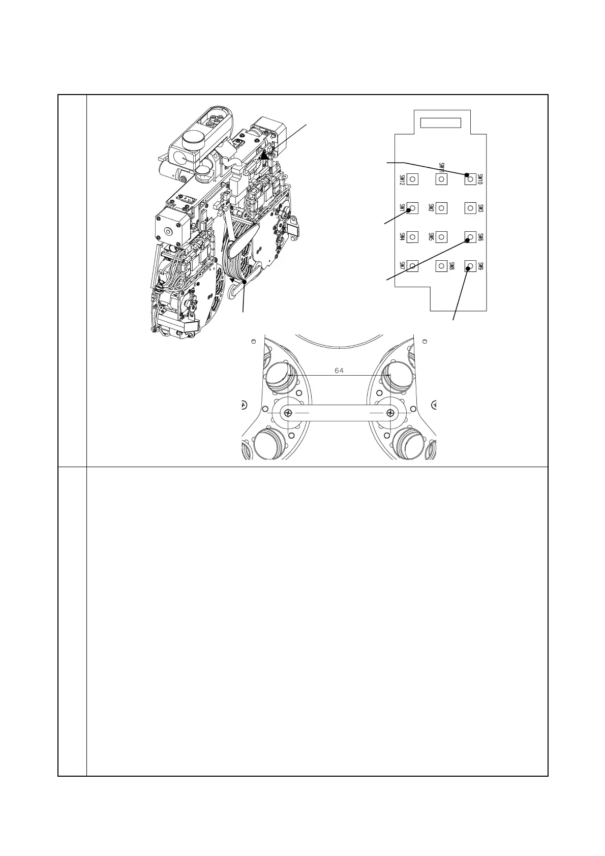
Illustration
Procedure
1. Set No. 1 of DIP SW to “ON” on the MAIN PCB.
2. Install the tool PCB to the MAIN PCB.
3. As pressing SW9 of the tool PCB, turn on the power.
4. Press SW10 and SW6 of the tool PCB to perform the zero position correction.
Perform the correction so that the PD position adjustment tool may be inserted.
(Use SW6 of the tool PCB to narrow the PD and SW10 to widen the PD.)
5. As pressing SW12 of the tool PCB, press SW4. (The correction value is written.)
6. After writing, perform the zero detection with SW1 to check if the PD position adjustment
tool is inserted.
PD position adjustment tool
Tool PCB mounting section
PD correction switch:
Clockwise
PD correction switch:
Counterclockwise