The RED wire of the motor should be connected into the “5” terminal.
2. Limit Switches
The YELLOW wire of the limit switches should be connected into the “8” terminal.
The BLACK wire of the limit switches should be connected into the “9” terminal.
The RED wire of the limit switches should be connected into the “10” terminal.
3. Warning Light (Included in some models, refers to the actual package)
One wire of the warning light should be connected into the “6” terminal, another should be connected into
the “7” terminal.
4. Start Capacitor
The two wires of the start capacitor should be connected into the “4”terminal and “5” terminal.
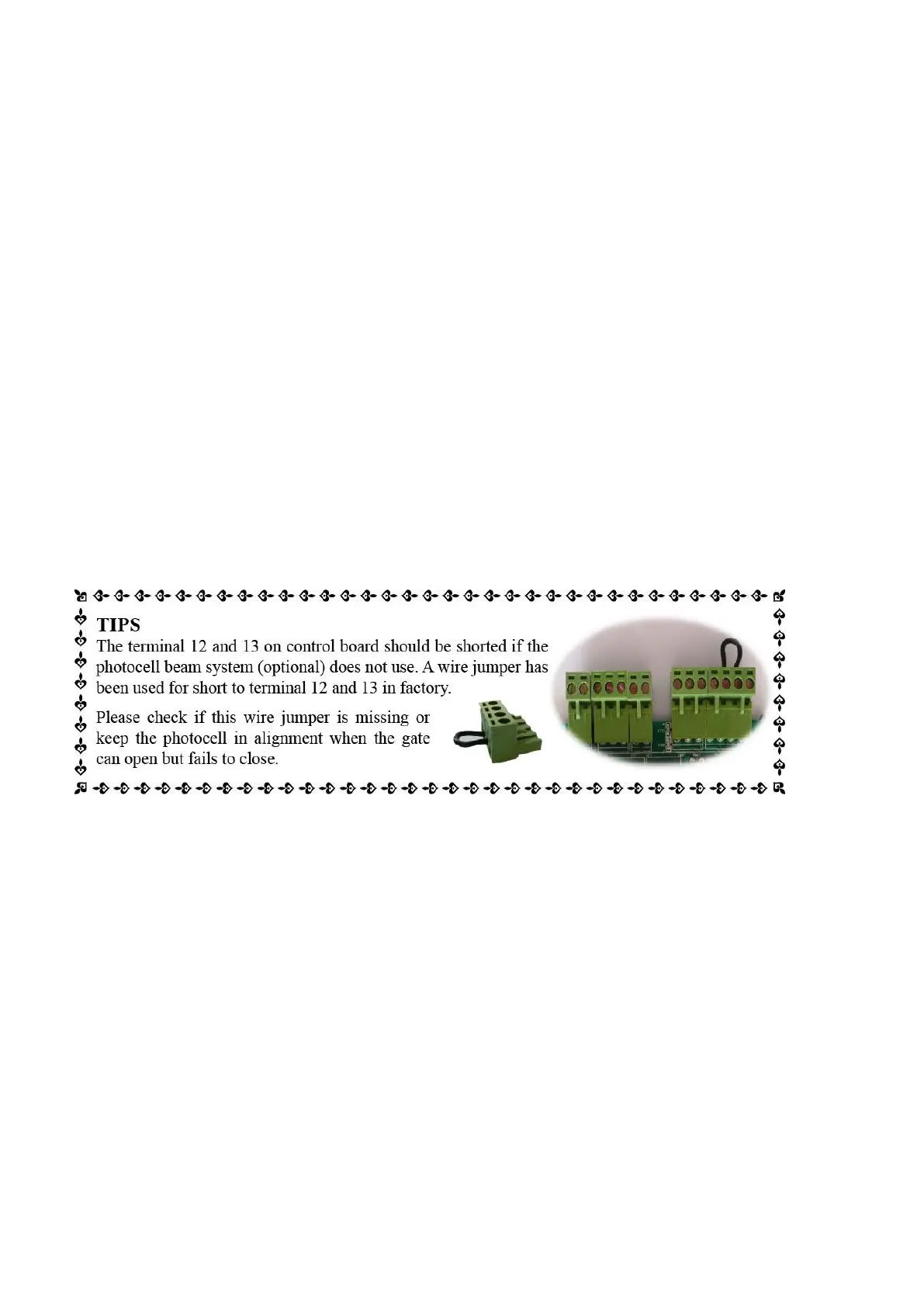
5. Photocell Beam System (PBS) (Included in some models, refers to the actual package)
Use a 2-core cable to connect the “+ ~” terminal of the photocell’s emitter to the “11” terminal, the “- ~”
terminal to the “13” terminal. Also the “+ ~” and “- ~” terminals of the photocell’s receiver should be
connected to the “11” and “13” terminals in parallel.
Use another 2-core cable to connect the “COM ” terminal of the receiver to the “13” terminal, the “NC”
terminal to the “12” terminal.
6. Reflection Photocell Sensor (optional)
The “AC10-25V/DC12-30V” terminals of the reflection photocell sensor should be connected to the “11” and “13”
terminals, no matter the polarity.
The “NC” terminal should be connected to the “12” terminal.
The “COM” terminal should be connected to the “13” terminal.
7. Wired Keypad (12VDC) (Optional)
The RED wire of the wired keypad should be connected into the “11” terminal.
The BLACK wire of the wired keypad should be connected into the “13” terminal.
The PURPLE wire of the wired keypad should be connected into the “13” terminal.
The BLUE wire of the wired keypad should be connected into the “14” terminal.
8. Push Button (Optional)
The push button should be wired to the “13” and “14” terminals. The gate operator works alternately by
pushing the button (open-stop-close-stop-open).
9. External receiver (optional)
The RED wire of the external receiver should be connected into the “11” terminal.
The BLACK wire of the external receiver should be connected into the “13” terminal.
The BROWN wire of the external receiver should be connected into the “14” terminal.
10. HomeLink Remote Control Kit (optional)
The “1” terminal should be connected to the “13” terminal.
The “2” terminal should be connected to the “14” terminal.
The “DC+” terminal should be connected to the “11” terminal.
The “DC-” terminal should be connected to the “13” terminal.