11. Exit Wand (optional)
The BLACK wire of the exit wand should be connected into the “15” terminal.
The BLUE wire of the exit wand should be connected into the “16” terminal.
The RED wire of the exit wand should be connected into the“11” terminal.
The GREEN wire of the exit wand should be connected into the“13” terminal.
The sensitivity adjustment board should be wired to the GREEN wire and the YELLOW wire of the wand. No
matter the polarity.
Setting of the Control Board
WARNING: Ensure the gate opener is Power Off when you make any adjustment of the gate
opener. Keep away from the gate during you set the gate opener system in case of the unexpected
gate moving. Carefully adjust the DIP switches to avoid the risk of machine damage and injury or
death. Always ask the help of professional technician /electrician if you have any question .
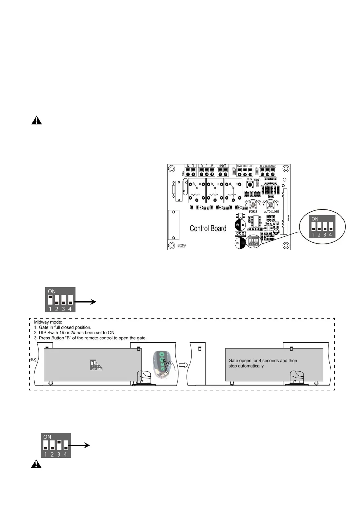
1. DIP Switches
The DIP switches are used to set the running
time of the motor in pedestrian mode,
enable/disable auto close function of the gate
operator and fast change the open/close
direction which is determined by the position
of the gate operator installed.
DIP Switch #1–#2: Running time of the
motor in Midway Mode
DIP Switch #1: ON – 2 Seconds OFF – 0
DIP Switch #2: ON – 4 Seconds OFF – 0
NOTE: The midway mode function would be disabled if both DIP switches are turned off. Factory
default setting is disabled. The midway mode could be activated by pressing button B of the remote
control when the gate is in the full closed position.
DIP Switch #3: Auto close function enabled/disabled
DIP Switch #3: ON – auto close function enabled
OFF –auto close function disabled
Important Note: When the auto close function is enabled, the photocell sensor is highly
recommended to be installed with the gate opener for safety.