8 Instructions for Use iMotion 2202 / 2301/ 2302 / 2401 T-1321 e
T1321_4e
3c 3a 3a
HK
inside outside
NK NK
5a, 7a
3d
3c
3d
3b 3b
1
4a
4c
8b
7c
7b 6a
6b
2a 4d 4b
8c
7d 7d
2a
8a
2b
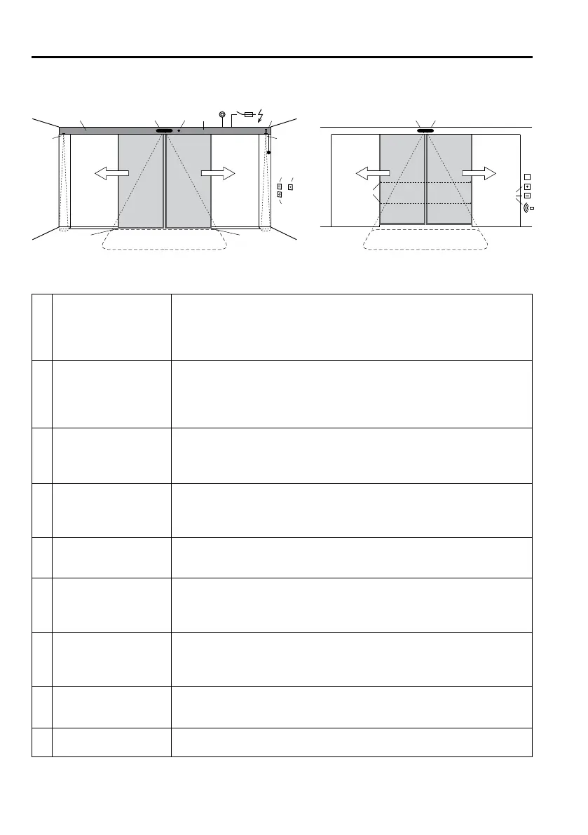
3 Product Description
3.1 System Overview
1 Drive
Cladding
Motor unit
MCU32 control system with monitoring system, power limitation and perma-
nent diagnosis
Guide system with noise-absorbent guide rail
2 Drive accessories u
£ Lock with
a) £ internal manual activation £ in the cladding £ on the wall
b) £ external manual activation
£ Emergency power supply via the battery unit
£ Mechanical emergency opening
3 Door leaves
a) Moving leaves with main closing edge (HK) and secondary closing edge (NK)
b) Moving leaves with floor guide
c) £ Side part u
d) £ Protection leaves u as protection for the secondary closing edge
4 Operating controls
a) £ iMotion user interface with 6 operating modes and fault display
b) £ Operating mode switch with 3 positions.
c) £ Lock for the user interface
d) £ Remote control of operating modes
5 Internal activators
a) With automatic activation b) With manual activation
£ Radar with/without direction recognition £ Push button
£ IR motion detector £ Contact-free button
6 External activators
a) With automatic activation b) With manual activation
£ Radar with/without direction recognition £ Key switch
£ IR motion detector £ Card reader
£ Remote control
7 Safety sensors
a) £ Presence sensor: main closing edge protection
b) £ Presence sensor, external: main closing edge protection
c) £ Safety beams
d) £ Presence sensors: secondary closing edge protection
8 Emergency systems
a) £ Power switch / fuse
b) £ Emergency on/off switch
c) £ Fire alarm system
9 Output message u
£ Bell / gong £ Light / ventilation £ Door locked
£ Door status ………………
£ Depending on the system’s equipment
 Loading...