13
3S SYSTEM “SOLUTION SAVING
SYSTEM” (OPTIONAL)
The need of an increasing carefulness to
the environment, and to the abuse of pol-
luting elements, such as detergents in the
oorcleaningmachines,hasbroughtusto
the realization of a device which, regard-
less from the capacity to use the machine
by theoperator,keepstheminimumow
of the detergent solution constant, hav-
ing been properly calibrated by an expert
technician.
The best detergent solution amount with
this system will be the one which realizes
theminimumowofdetergentsolution
sufcienttocleancorrectlytheoor.
For this reason the system is called “Solu-
tion Saving System” abbreviated to “3S”
system.
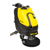
The system is composed by a hydraulic
circuit parallel to the traditional one which
can be enabled or disabled directly from
the instrument board through a 3-position
switch with the following functions:
(1) = Position solution valve with tradi-
tionalfunctioningwithvariablewaterow
that differs by the opening of the solution
valve.
(2) = Position STOP with functioning
withoutow(dryingonly).
(3) = Position 3S with functioning with
optimalxedow.
The hydraulic circuit of the 3S system
is independent and it is provided with
aproperlterwhichhastobecleaned
regularly.
For the cleaning it is necessary to unscrew
theplugasshowninthegureandclean
theinsidelterwithawaterjet.
FLOOR CLEANING
CONNECTION OF THE BATTERIES
TO THE MACHINE
Plug in the batteries connector (1) to the
machine connector (2), placed in the rear
part of the machine.
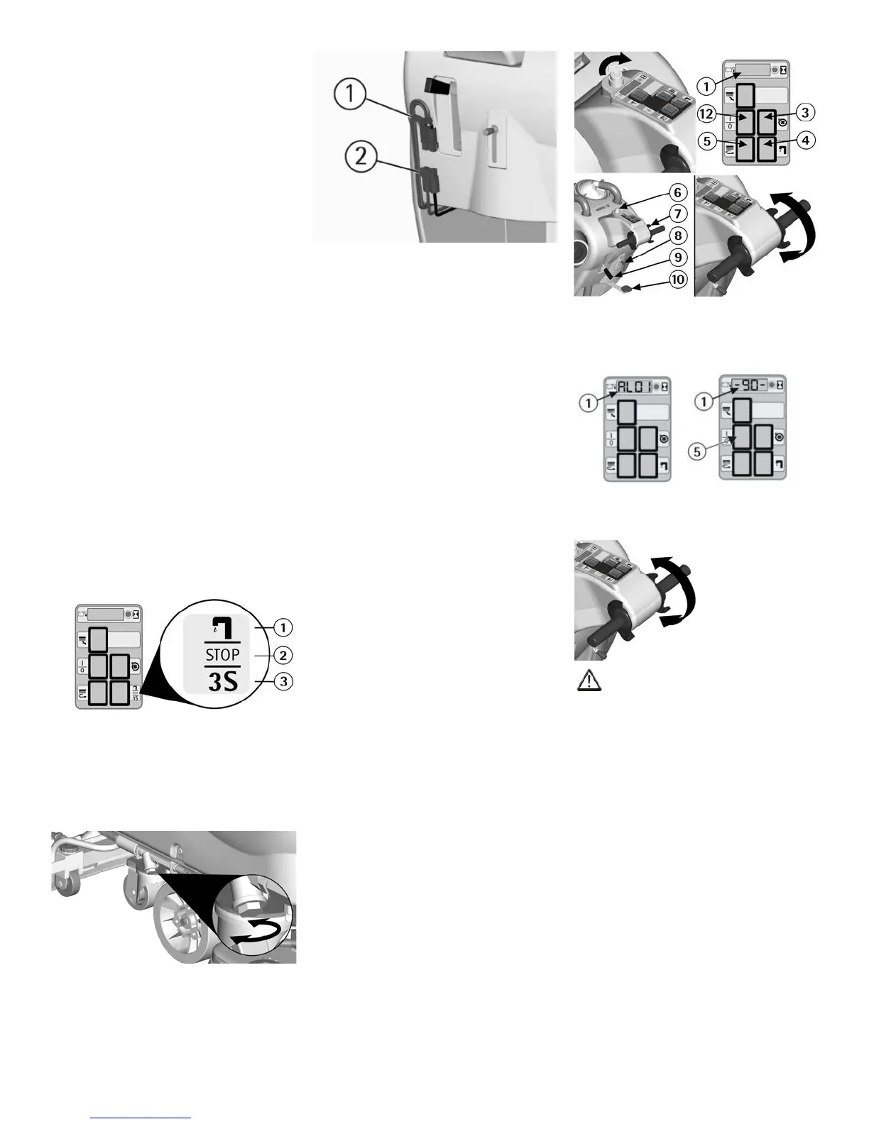
STARTING OF THE MACHINE
1. Switch on the machine acting upon
the general switch (12). For machines
equipped with key switch (see under "OP-
TIONAL ACCESSORIES”), turn the key
(6) clockwise.
2. Press the brush motor switch (5).
3. Check the battery type and the charge
level on the display (1).
4. Press the suction motor switch (3).
5. Acting upon the solution valve lever
(8) adjust the solution detergent quantity
bringingtheooruniformlywet,avoiding
the leakage of detergent from the splash
guard. Always consider that the correct
quantity of solution detergent depends on
thetypeofoor,dirtinessandmachine
speed.
Acting upon this lever, the indicator on
the instrument board of the open solution
valve (4) will turn on.
For machines optionally equipped with
solenoid valve (see under “OPTIONAL
ACCESSORIES”)theowofdetergent
solution will be activated automatically,
once the solution valve has been opened
through the lever (8), acting upon the
brush activation levers (7). Releasing
theselevers,owwillstopautomatically.
Models equipped with the 3S system (op-
tional), it is necessary to press the suitable
switch to activate the detergent solution
supply by choosing between the traditional
adjustment system through the solution
valveorthesystemofxedoptimumsup-
ply (see under “3S SYSTEM SOLUTION
SAVING SYSTEM”).
6. Acting upon the brush base lifting pedal
(10) lower the brush base.
7. Acting upon the squeegee lifting lever
(9) lower the squeegee.
8. Activating the levers (7) the brush will
start rotating moving the machine a for-
ward movement. The squeegee will start
dryingtheoor.
9.Duringtherstfeet/meterscheckthat
thedetergentsolutionowisappropriate
and that the squeegee adjustment guaran-
tees a perfect drying action.
FORWARD MOVEMENT
By activating the levers (7), the
brush will start rotating resulting in
the machine’s forward movement.
STOP
Releasing the brush activationilevers , the
machine and the brushes will stop.
ATTENTION:
Moving the machine backwards, make
sure that the squeegee is lifted.
ADJUSTMENT OF THE BRUSH
PRESSURE
Through the register (1) placed on the
internal part of the front right wheel, it is
possible to adjust the brush pressure on
the cleaned surface. By turning the wing
nut clockwise the pressure increases, ro-
tating the wing nut counterclockwise, the
pressure decreases. This device allows
amoreefcientcleaningactionalsoon
verydifcultanddirtysurfaces.