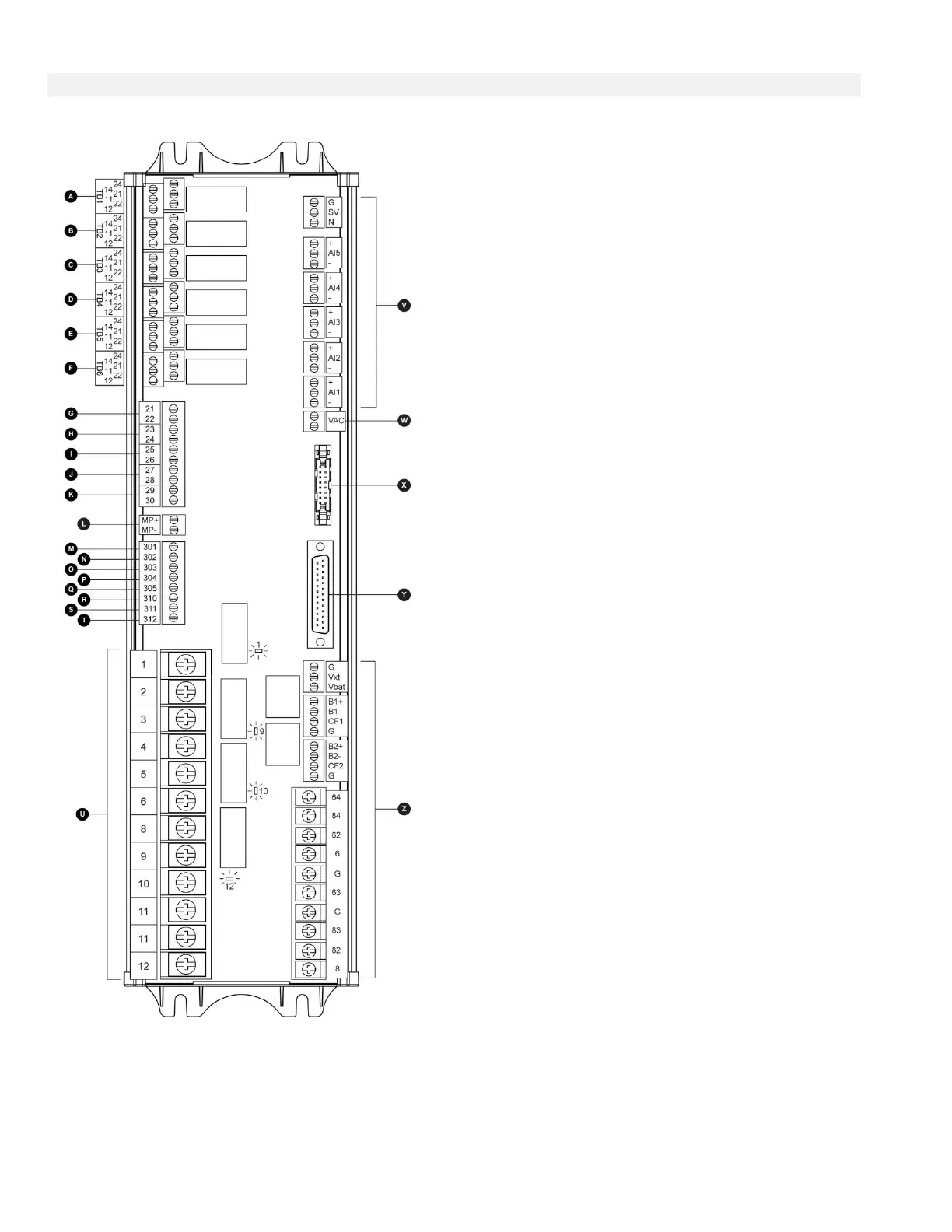
A-F : Alarm Output Terminals
(DPDT Relay, 11/21:Common, 12/22:Normally Closed,
14/24:Normally Open):
A: Controller Trouble (Fail safe)
B: Engine Run
C: Main SS in HAND/OFF position
D: Engine Trouble
E: Pump Room Alarm
F: Optional Output 1
G-T : Field Input Terminal
(Dry Contact Only: Voltage Free):
G: Low Fuel Level (NO)
H: Remote Automatic Start (NC)
I: Deluge Valve Start (NC)
J: Fuel Tank Leak (NO)
K: High Fuel Level (NO)
L: Engine RPM Magnetic Pickup
M: ECMS Elec. Ctrl. Switch
N: FIM Fuel Injection Malfunction
O: ECMW Elec. Ctrl. Warning
P: ECMF Elec. Ctrl. Fault
Q: PLD Low Suction Pressure
R: High Raw Water Temperature
S: Low Raw Water Flow
T: LET Low Engine Temperature
U : Engine Terminals :
The terminals are numbered according to the standard:
1 - FS : Fuel Solenoid Valve
(ETR - Energized To Run)
2 - ER : Engine Run contact
3 - OS : Engine Overspeed contact
4 - OP : Engine Oil Pressure contact
5 - WT : Engine Coolant Thermostat contact
6 - B1 : Battery #1 positive
8 - B2 : Battery #2 positive
9 - C1 : Start Contactor #1
10 - C2 : Start Contactor #2
11 - GND : Ground
12 - ST : Stop Fuel Solenoid Valve
(ETS - Energized To Stop)
V: Analog inputs / Solenoid Valve:
SOL V: Test Solenoid Valve
AI1: Discharge Pressure transducer
AI2: Optional additional Discharge Pressure transducer
AI3: Water Level or Suction Pressure transducer
AI4: Fuel Level analog input
AI5: Flow or Spare Temperature analog input
W: Optional Input for analog AC reading
X: CANBUS to IO cards
Y: CANBUS to ViZiTouch
Z: Factory reserved power connections