I: The alarm/warning notification.
Warning indicator: Exclamation mark in a yellow round icon. If no alarm is in ACTIVE condition on the controller and
at least one warning is ACTIVE or OCCURRED, the warning indicator will be present.
Alarm indicator: Exclamation mark in a red triangle icon. As soon as at least one alarm is ACTIVE or OCCURRED,
the alarm indicator will be flashing.
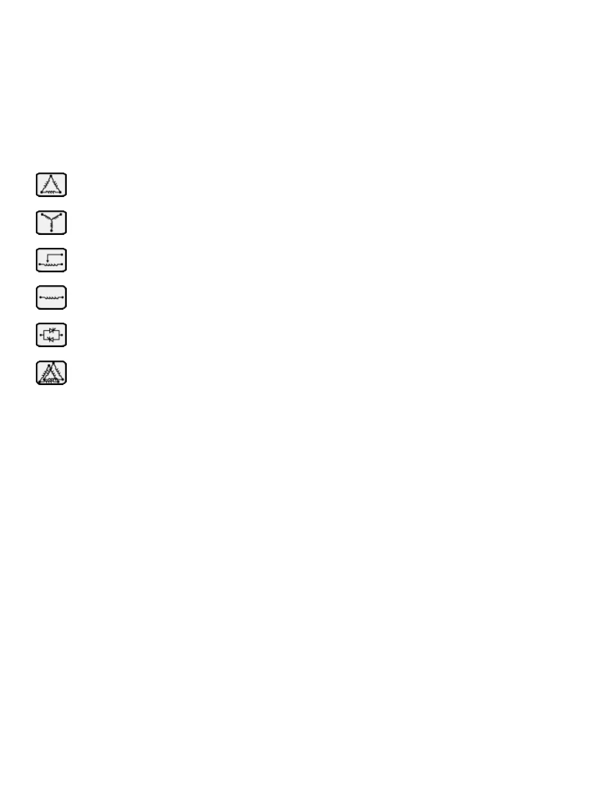
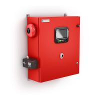
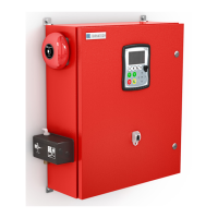
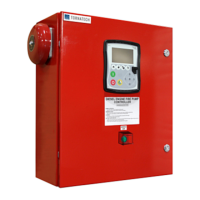
J: The motor configuration symbol shows how the motor is wired to the contactor(s). This symbol is used to show if
the motor is in a starting configuration (Wye wiring, for example) or in a permanent running configuration (i.e. delta
wiring)
K: Representation of the motor starting or stopping cause. A green capsule will indicate the reason why the motor is
running. Possible choices are:
EMERGENCY: Manual motor starting activated by the emergency handle.
MANUAL: Manual motor starting activated by the START push button.
REMOTE MANUAL: Manual motor starting activated by a remote start contact.
DELUGE: Automatic motor starting activated by a deluge valve.
AUTO: Automatic motor starting activated by pressure drop
REMOTE AUTO: Automatic motor starting activated by remote equipment
FLOW: Automatic motor starting activated by a signal in the FLOW/ZONE START/STOP input.
HIGH ZONE: Automatic motor starting activated by a signal in the FLOW/ZONE START/STOP input.
WEEK TEST: Automatic motor starting activated by a scheduled test.
MANUAL TEST: Automatic motor starting activated by the run test push button.
A red capsule will indicate the reason why the motor is not running despite the fact that a request is being made.
Possible choices are:
LOAD SHED: The transfer switch has transferred to the alternate position and the motor starting is delayed to
reduce the load on the alternate power source. This functionality is optional.