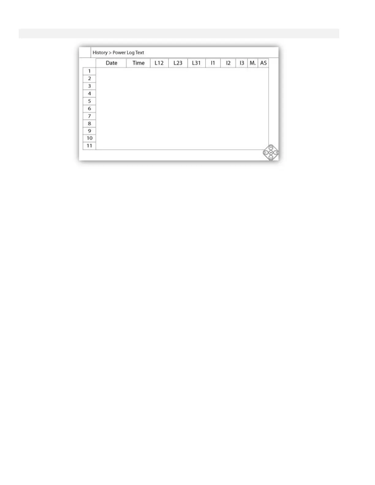
The “Power Log text” shows a table with 10 rows. The total number of rows available is 500 and the logs are sorted
in chronological order. To see more logs, please download all logs on a USB Device.
Description of the columns :
-Date: Date when the log was recorded
-Time: Time when the log was recorded
-L12: The phase voltages in this column represent an individual phase voltage between line 1 and line 2.
-L23: The phase voltages in this column represent an individual phase voltage between line 2 and line 3.
-L31: The phase voltages in this column represent an individual phase voltage between line 3 and line 1.
-I1: Current value of line 1
-I2: Current value of line 2
-I3: Current value of line 3
-M.: The cell will become green if the motor was running for that specific power log.
-AS: In the case of fire pump models built with an automatic transfer switch, the cell will become green if the logged
phase voltages were read from the Alternate Side of the controller.
The contextual navigation pad is implemented in this page. It allows for quick navigation functions, like “Page Up”,
“Page Down”, “First Page”, “Last Page” and “Graphical Mode”. As always, clicking on the Navigation Pad Icon in the
lower right corner of the screen will pop-up the Navigation Pad functions specific for this page. By pressing these
buttons, the displayed rows will shift, allowing a quick user-friendly navigation.