g003320
Figure5
1.Counterweight
PositioningtheTurfCompensating
SpringandInstallingtheHose
Guide
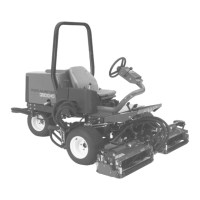
CuttingUnits4
g375671
Figure6
1.Cuttingunit15.Cuttingunit5
2.Cuttingunit2
6.Reelmotor
3.Cuttingunit3
7.Weight
4.Cuttingunit4
1.Ifthehairpinisinstalledintherearholeofthe
compensation-springrod—removethehairpin
andinsertitintheholenexttothebracket
(Figure17).
g375689
Figure7
1.Hairpin
2.Removethe2angelocknuts(3/8inch)and2
carriagebolts(3/8x1-1/4inches)thatsecure
theturf-compensatorbrackettothecutting-unit
frame(Figure18).
g375690
Figure8
1.Carriagebolt(3/8x1-1/4
inches)
3.Flangelocknut(3/8inch)
2.Turf-compensatorbracket
3.Removetheangelocknut(3/8inch)that
securesthecapscrewoftheturfcompensation
springtotherighttabofthecarrierframe,
andremovethecompensationspringfromthe
cuttingunit(Figure19).
Note:Donotremovetheangeserratednut
fromthecapscrew.
12