Reelmaster 7000- D Hydraulic SystemPage 5 - 131
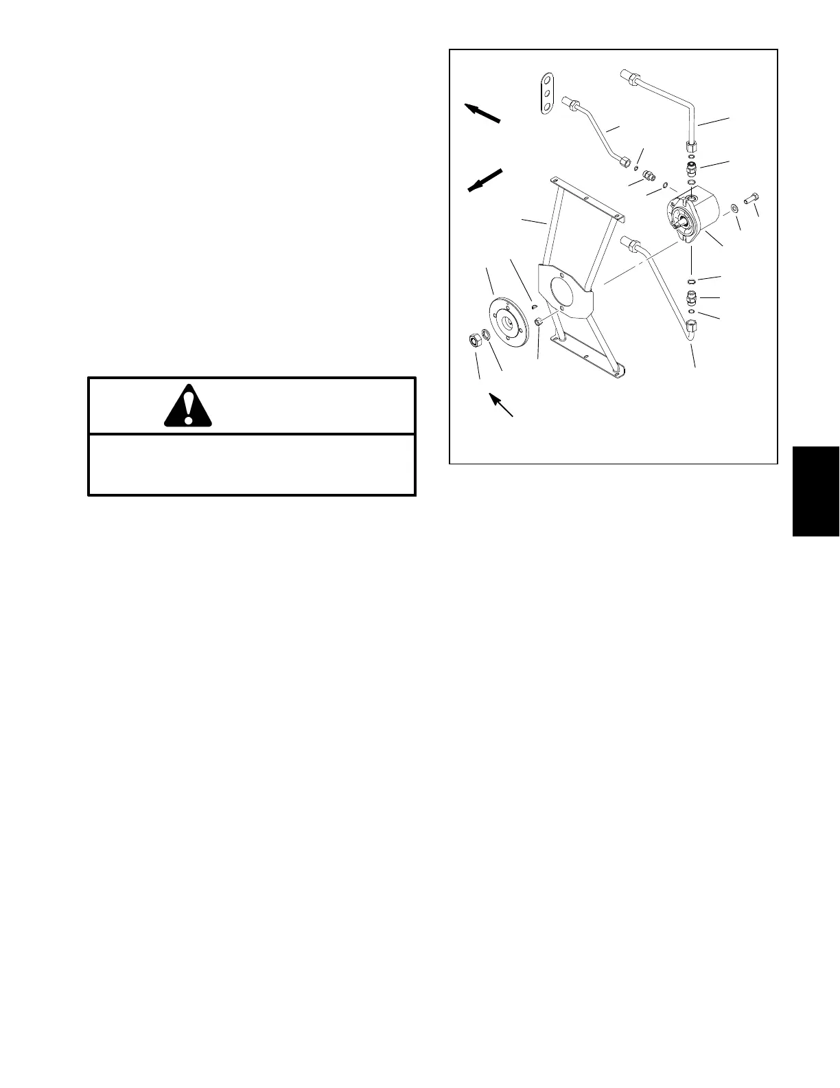
Removal (Fig. 85)
1. Park machine on a level surface, lower cutting units,
stop engine, apply parking brake and remove key from
the ignition switch.
2. Read the General Precautions for Removing and
Installing Hydraulic System Components in this chapter.
3. Unlatch and raise hood.
4. Remove air cleaner intake hose from air cleaner.
5. Remove flange head screws and flange nuts that se-
cure plenum assembly (item 1) to crossover plate. Re-
move plenum with air cleaner hose and drain hose
attached.
6. Remove four (4) cap screws (item 18) and washers
used to secure fan to fan hub. Remove fan.
CAUTION
The radiator and engine may b e hot. To avoid
possible burns, allow the engine and cooling
systems to cool before removing fan motor.
7. Remove upper fan shroud:
A. Clean junction of hydraulic tubes on right side of
upper radiator shroud. Loosen and separate hy-
draulic tubes that lead to hydraulic fan motor.
B. Remove bulkhead nuts (item 6) that secure hy-
draulic tubes to upper fan shroud. Slide outer sup-
port shim (item 5) from tubes.
C. Remove fasteners that secure upper fan shroud
to lower fan shroud and radiator. Carefully lift upper
shroud from machine.
D. Put caps or plugs on disconnected hydraulic
tubes to prevent contamination.
8. Remove fasteners that secure lower fan shroud to
radiator and remove lower fan shroud from machine.
IMPORTANT: Make sure to not damage the radiator
or other machine components while loosening and
removing the fan motor and bracket assembly.
9. Remove six (6) cap screws (item 15) and flange nuts
that secure fan motor bracket to r adiator. Carefully re-
move fan motor, hydraulic tubes and bracket assembly
from machine and place o n suitable work surface.
1. Fan motor bracket
2. Hex nut
3. Lock washer
4. Fan Hub
5. Woodruff key
6. Lock nut (2)
7. Hydraulic tube
8. Hydraulic tube
9. Hydraulic tube
10. Fan motor
11. Flat washer (2)
12. Cap screw (2)
13. Hydraulic fitting (2)
14. O- ring (2)
15. O- Ring (2)
16. Hydraulic fitting
17. O- ring
18. O- ring
Figure 86
FRONT
RIGHT
27 to 33 ft- lb
(37to44N-m)
1
2
3
4
5
6
7
8
9
10
11
12
13
14
15
16
13
17
18
10.Remove fan motor from bracket (Fig. 86):
A. Disconnect hydraulic tubes (items 7, 8 and 9)
from fan motor fittings. Label hydraulic tubes for
proper assembly.
B. Remove hex nut (item 2) and washer that secure
fan hub to fan motor. Use suitable puller to carefully
remove fan hub from fan motor shaft. Locate and re-
trieve woodruff key (item 5).
C. Remove two (2) cap screws (item 12), flat wash-
ers and lock nuts that secure fan motor to fan motor
bracket. Remove fan motor from bracket.
D. If necessary, remove hydraulic fittings from fan
motor and discard O- rings.
Hydraulic
System
 Loading...


