Reelmaster 7000−D Page 6 − 53 Electrical System
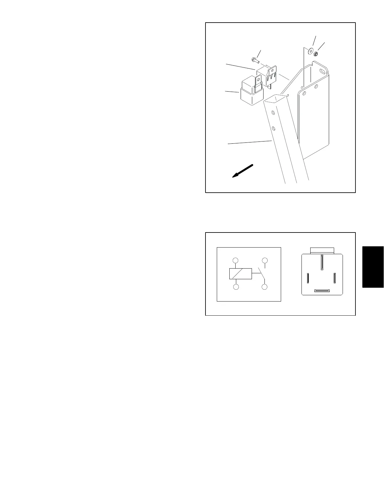
5. Using a multimeter, verify that coil resistance be-
tween terminals 86 and 85 is approximately 72 ohms
(Fig. 57).
6. Connect multimeter (ohms setting) leads to relay ter-
minals 30 and 87. Ground terminal 86 and apply +12
VDC to terminal 85. The relay should make and break
continuity between terminals 30 and 87 as +12 VDC is
applied and removed from terminal 85 (Fig. 57).
7. Disconnect voltage and test leads from the relay ter-
minals.
8. If testing determines that the relay is not functioning
correctly, replace the relay.
9. If the relay tests correctly and a circuit problem still
exists:
A. Check wire harness (see Electrical Schematic
and Wire Harness Drawings in Chapter 10 − Foldout
Drawings in this manual).
B. Use the InfoCenter Display to check specific TEC
output operation (see InfoCenter Display in this
chapter).
10.Secure relay to mounting bracket and connect wire
harness connector to relay.
11.Secure all removed components to machine.
12.Connect positive (+) cable to battery and then con-
nect negative (−) cable to battery (see Battery Service
in this chapter).
1. Air cleaner mount
2. Start relay (5 terminal)
3. Glow relay (4 terminal)
4. Screw (2)
5. Washer (2)
6. Lock nut (2)
Figure 56
FRONT
KUBOTA DIESEL ENGINE
1
2
3
4
5
6
Figure 57
86 87
85 30
85 86
87
30
Electrical
System
 Loading...


