Reelmaster 7000−D Page 8 − 13 Chassis
Removal (Fig. 10)
1. Park machine on a level surface, lower cutting units,
stop engine, apply parking brake and remove key from
the ignition switch.
2. Disconnect seat electrical connector from machine
wire harness.
3. Support console arm assembly to prevent it from
shifting.
4. Remove flange nut and carriage screw (item 6) that
secure support channel (item 11) to front left corner of
seat.
5. Remove cap screw (item 7) that secures console
arm support (item 10) to coupling nut (item 8).
6. Remove cap screw (item 1), flat washer (item 4),
spacer (item 2) and seat belt buckle (item 3) from seat
and console arm support (item 10).
IMPORTANT: Make sure to not damage the electri-
cal harness, control cable or other parts while mov-
ing the console arm assembly.
7. Carefully move console arm assembly away from
seat. Support console arm to prevent it from falling.
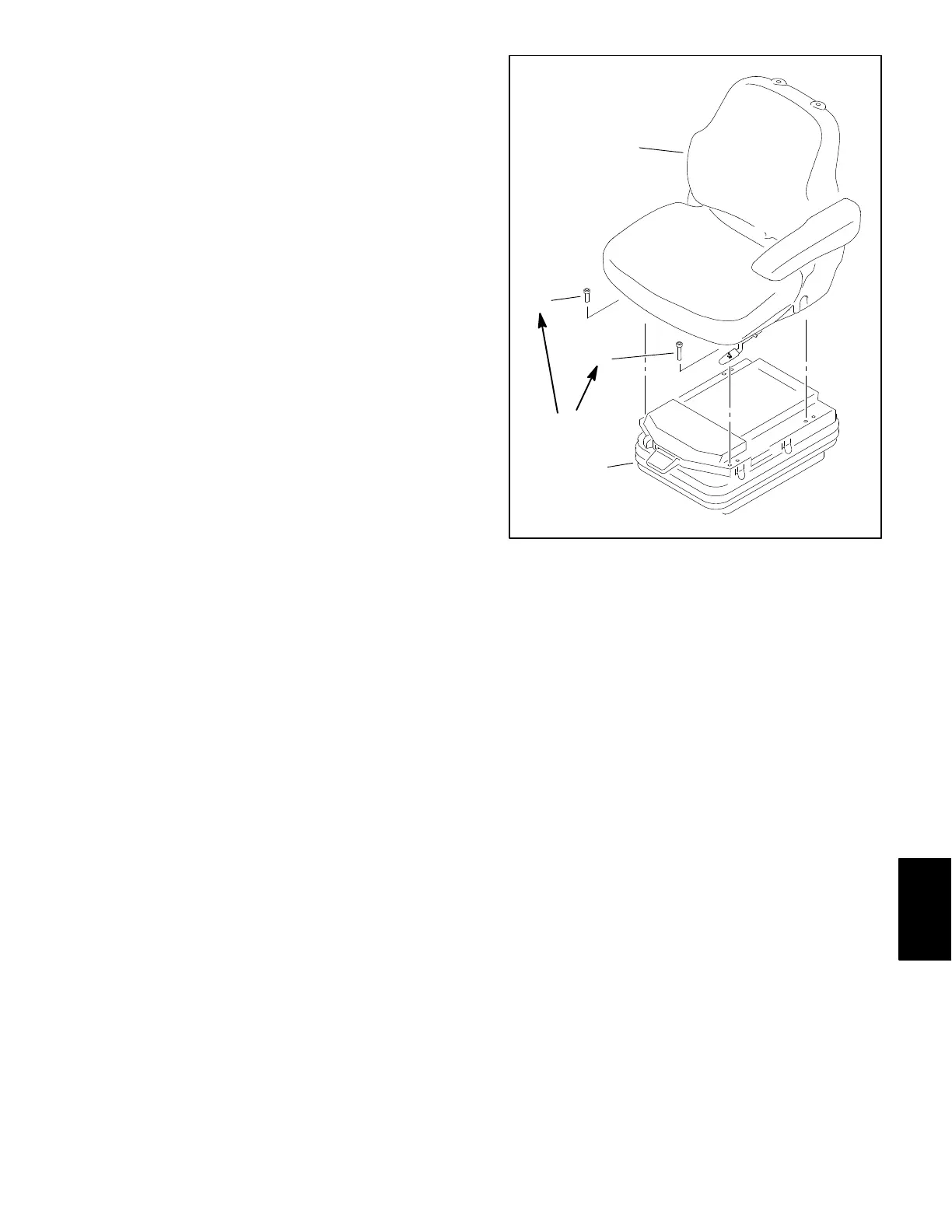
8. Remove four (4) torx head screws that secure seat
to seat suspension (Fig. 11).
9. Lift seat from seat suspension and remove from ma-
chine.
Installation (Fig. 10)
1. Carefully position seat to seat suspension.
2. Secure seat to seat suspension with four (4) torx
head screws (Fig. 11). Make sure that longer screw is
positioned near the seat adjustment handle. Torque
screws 18 ft−lb (25 N−m).
IMPORTANT: Make sure to not damage the electri-
cal harness, control cable or other parts while mov-
ing the console arm assembly.
1. Seat
2. Suspension assembly
3. Screw − M8x12 (3)
4. Screw − M8x16
Figure 11
18 ft−lb
(25 N−m)
1
2
3
4
3. Position and secure console arm assembly to seat.
Install all fasteners before fully tightening them.
A. Place flat washer (item 4), seat belt buckle
(item 3) and spacer (item 2) between seat and con-
sole arm support (item 10). Secure with cap screw
(item 1).
B. Secure console arm support (item 10) to coupling
nut (item 8) with cap screw (item 7).
C. Secure support channel (item 11) to front left cor-
ner of seat with flange nut and carriage screw
(item 6).
D. Fully tighten all fasteners to secure console arm
assembly to seat.
4. Connect seat electrical connector to machine wire
harness.
Chassis
 Loading...


