Reelmaster 7000--D
DPA Cutting Units
Page 9 -- 48
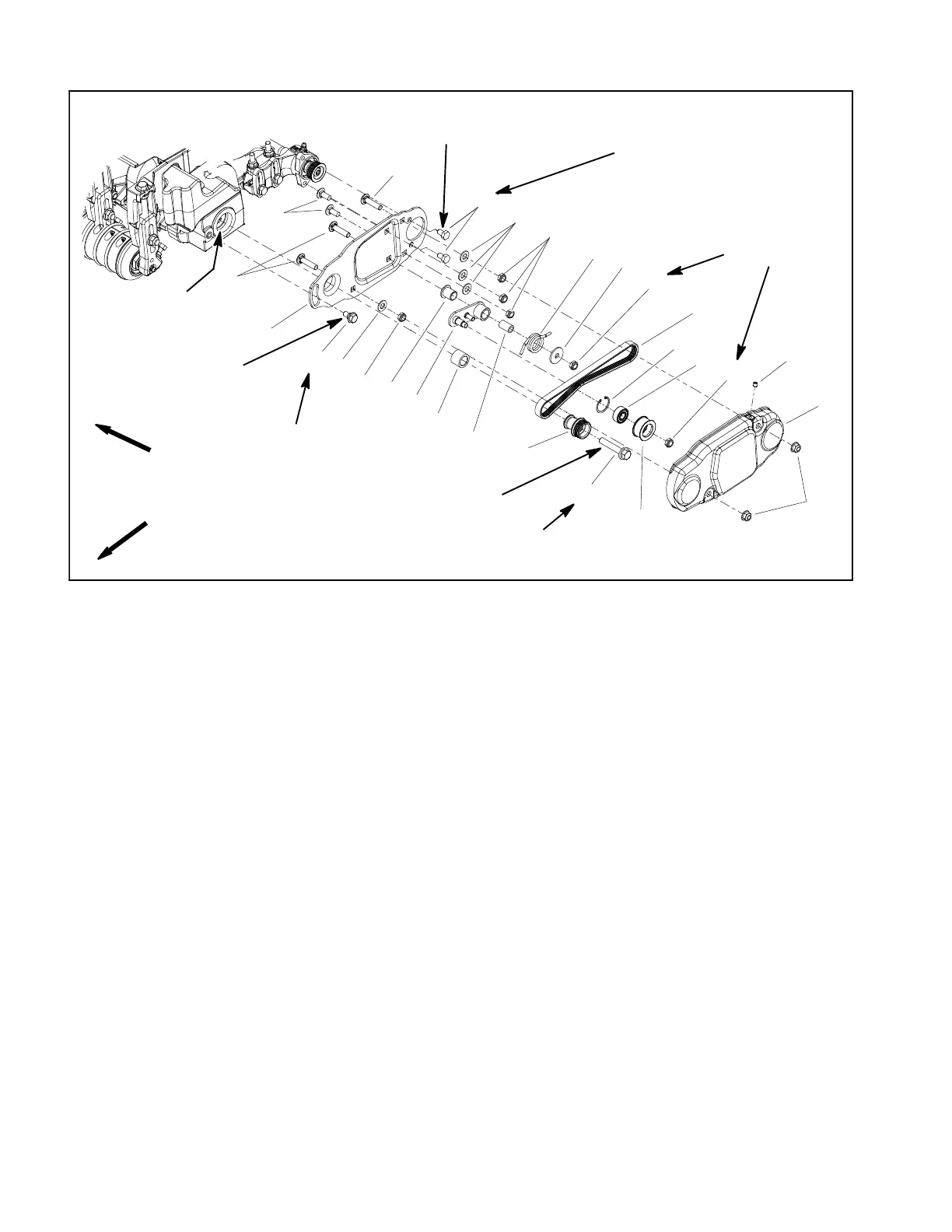
Drive System Disassembly (Fig. 68)
1. Carriage screw (2 used)
2. Carriage screw (3 used)
3. Brush plate
4. Cap screw (2 used)
5. Flat washer (4 used)
6. Lock nut (6 used)
7. Idler arm
8. Idler spacer
9. Idler spring
10. Pivot washer
11. Drive belt
12. Idler pulley
13. Retaining ring
14. Bearing
15. Shoulder screw
16. Flange head screw
17. Drive pulley
18. Spacer
19. Flange bushing
20. Cover
21. Flange nut (2 used)
22. Set screw (top of cover only)
Figure 68
FRONT
RIGHT
10 to 15 ft--lb
(14to20N--m)
35 to 40 ft--lb
(48 to 54 N--m)
2
3
6
8
9
10
11
13
1
5
7
12
14
15
16
17
18
19
20
4
6
6
2
5
6
21
15 to 19 ft--lb
(20to25N--m)
Loctite #243
22
Loctite #243
15 to 19 ft--lb
(20to25N--m)
Loctite #243
Grease
Grommet ID
NOTE: Drive components for the rear roller brush are
located on the opposite side of the cutting unit from the
cutting reel motor. Figure 56 shows components used
when the brush drive is on the left side of the cutting unit.
NOTE: The Installation Instructions for the rear roller
brush kit has detailed information regarding assembly
and adjustment. Use those Instructions along with this
Service Manual when servicing the rear roller brush.
1. Position machine on a clean and level surface, lower
cutting units, stop engine, engage parking brake and re-
move key from the ignition switch.
2. Remove cover (item 20) to access rear roller brush
drive components.
3. Remove roller brush drive components as neces-
saryusingFigure68asaguide.
4. Remove roller brush drive shaft if needed:
A. Remove socket head screws that secure drive
housing to cutting unit side plate and remove hous-
ing from cutting unit.
IMPORTANT: If rear roller brush drive is on left
side of cutting unit, drive shaft has left hand
threads and can be identified by a groove on the
flange. If the rear roller brush drive is on right
side of cutting unit, drive shaft has right hand
threads and does not have a groove on the flange
(Fig. 70).
B. Loosen and remove drive shaft from cutting reel.
 Loading...


