Reelmaster 7000--DUniversal Groomer (Optional) Page 11 -- 12
Idler Assembly
1
2
3
4
5
6
7
8
9
9
10
13
11
12
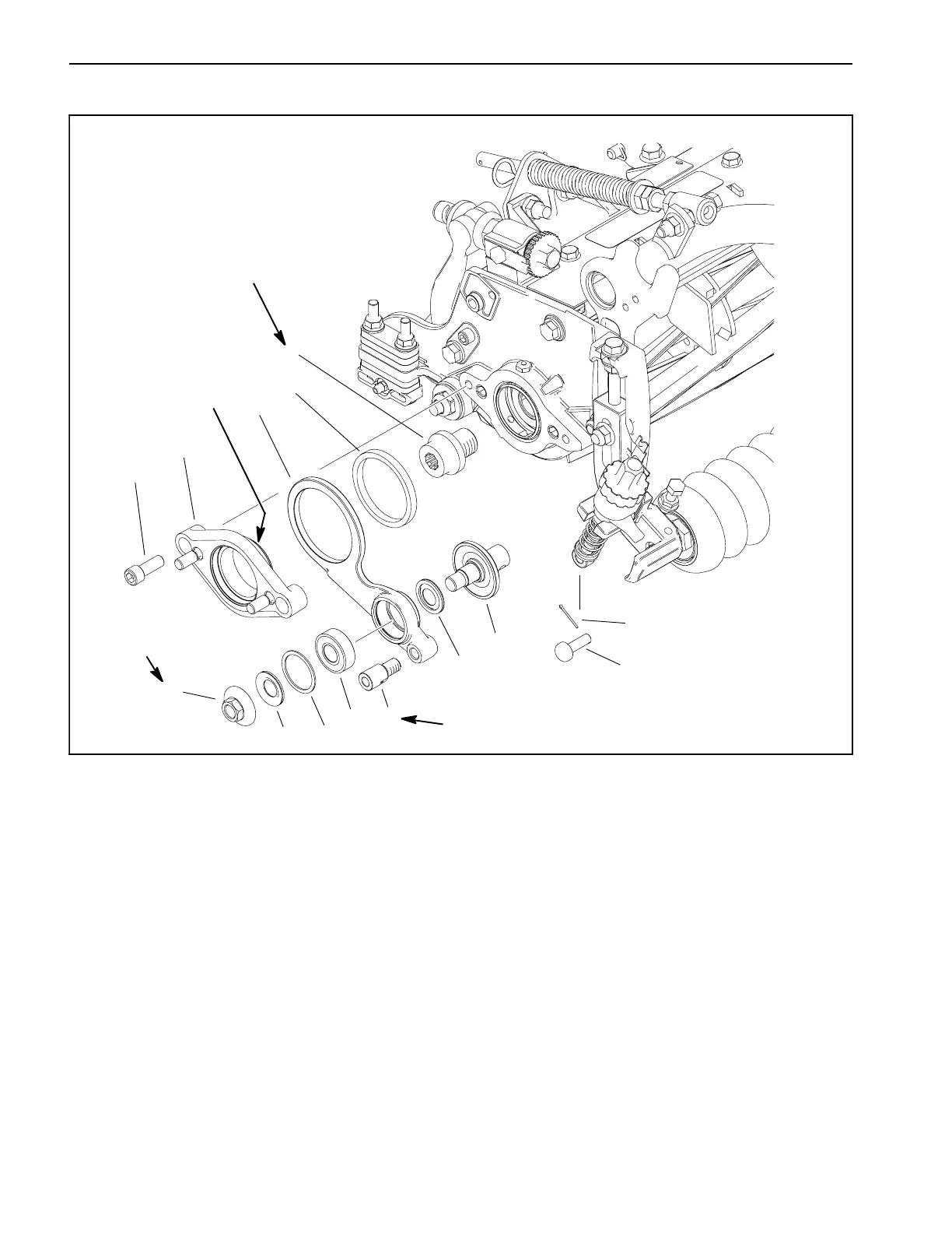
Figure 9
1. Socket head screw (2)
2. Pivot hub
3. Idler arm
4. Bushing
5. Threaded insert
6. Cotter pin
7. Clevis pin
8. Stub shaft and shield
9. Bearing shield (2)
10. Bearing
11. Retaining ring
12. Flange nut
13. Collar
Antiseize
Lubricant
85 to 95 ft--lb
(115 to 129 N--m)
Loctite #242
27 to 33 ft--lb
(37 to 45 N--m)
24 to 30 ft--lb
(33 to 41 N--m)
NOTE: The groomer idler assembly is located on the
same side of the cutting unit as the cutting unit hydraulic
motor.
Removal (Fig. 9)
1. Park machine on a clean and level surface, lower
cutting units completely to the ground, stop engine, en-
gage parking brake and remove key from the ignition
switch.
2. Remove hydraulic reel motor from cutting unit (see
Hydraulic Reel Motor Removal in Chapter 9 -- Cutting
Units in this manual).
3. Remove the groomer reel assembly (see Groomer
reel in this chapter).
4. Remove the cotter pin and clevis pin from the height
adjustment rod at the front of the idler arm. Discard cot-
ter pin.
5. Remove the socket head cap screws securing the
pivot hub to the cutting unit and remove the pivot hub
and idler assembly from the cutting unit.
6. Inspect shields, bearing and bushing in idler assem-
bly. Remove and discard damaged or worn compon-
ents.
 Loading...


