Greensmaster Flex 21Groomer (Model 04201) (Rev. B) Page 8 – 14
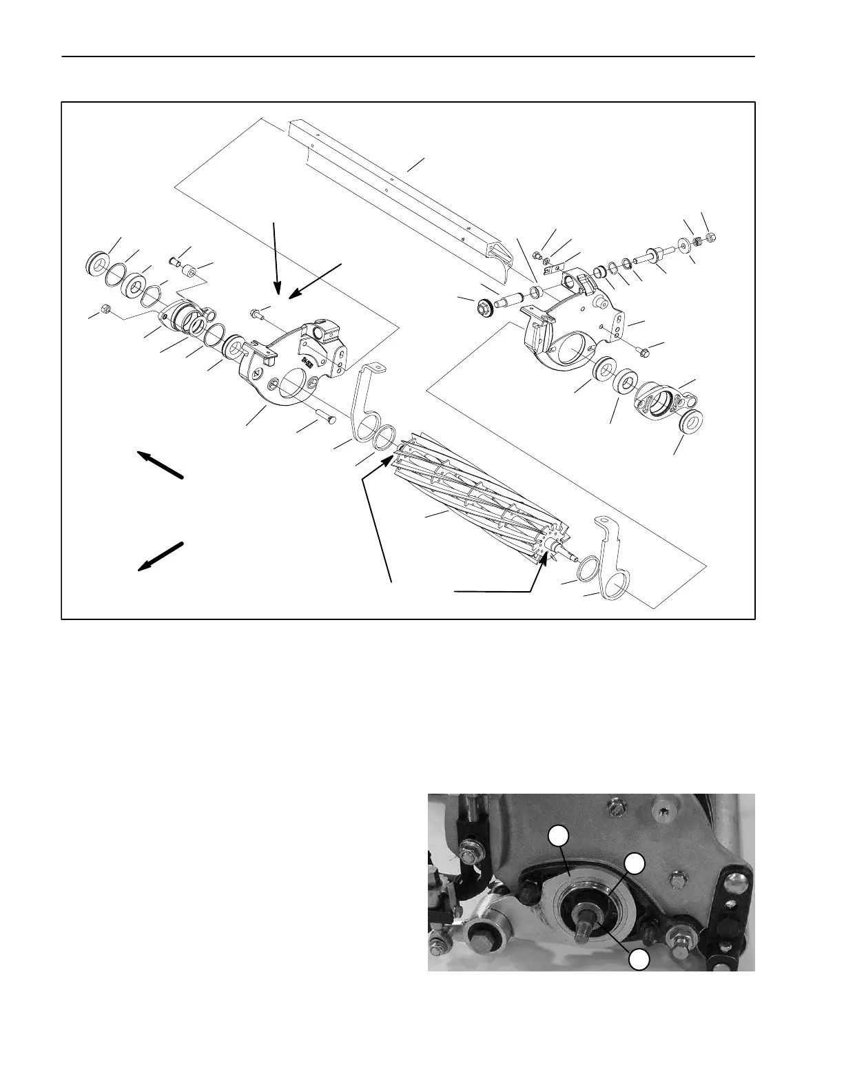
Cutting Reel
1. Shield frame
2. Adjust nut
3. Bedbar adjuster nut
4. Flange bearing
5. Cap screw
6. Lock washer
7. Detent
8. Spring wave washer
9. Retaining ring
10. Bedbar adjuster screw
11. Washer
12. Compression spring
13. Lock nut
14. LH side plate
15. Flange head screw
16. Outer oil seal
17. Reel bearing housing
18. Ball bearing
19. RH side plate
20. Plow bolt
21. Retaining ring
22. Tapered nut
23. Wave washer
24. Nylon bushing
25. Bushing
26. Reel assembly
27. Bushing
28. LH pitch arm
29. RH pitch arm
30. Washer (if equipped)
31. Inner oil seal
Figure 19
16
21
18
23
24
25
22
21
31
15
2
3
4
5
6
7
4
8
9
10
11
12
13
14
15
31
18
17
16
29
27
26
27
20
17
28
Anti–seize lubricant
FRONT
RIGHT
160 to 175 in–lb
(182 to 200 kg–cm)
1
19
Threadlocking
Compound
30
Removal (Fig. 19)
1. Remove cutting unit from machine (see Separating
Cutting Unit from Traction Unit in the General Informa-
tion section of Chapter 7 – Cutting Unit). Place cutting
unit on a flat level surface or on a stable work bench.
2. Remove groomer reel (see Groomer Reel Removal
in this section) and LH groomer side plate (see Groomer
Reel Bearing Replacement in this section) from cutting
unit.
3. Slide spacers from LH reel shaft and LH reel bearing
housing (Fig. 20).
1. Groomer LH side plate
2. Reel shaft spacer
3. Reel housing spacer
Figure 20
3
1
2
 Loading...


