Greensmaster Flex 21 Traction and Reel Drive System (Rev. C)Page 4 – 31
Gearbox Disassembly (Fig. 40)
1. Clean outside of the gearbox assembly.
2. Remove reel drive assembly from gearbox (Fig. 41):
A. Loosen flange nut that secures reel drive pulley to
gearbox clutch shaft.
B. Remove reel drive belt (see Reel Drive Belt Re-
placement).
C. Remove flange nut from gearbox shaft and slide
pulley from shaft. Take woodruff key from shaft.
3. Pull drive shaft plate from gearbox after removing
three fasteners: two socket head screws and one cap
screw with lockwasher.
4. Remove any burrs from axle and clutch shafts.
5. Loosen locknut that is used to secure traction lever
to the traction shaft. Remove lever. Note that lever and
shaft splines identify correct lever location on shaft.
6. Loosen and remove four remaining socket head
screws and washers that secure gearbox cover to base.
NOTE: Gearbox cover removal will be easier by lightly
lubricating external extensions of axles and shafts.
7. Pull gearbox cover from gearbox base taking care
not to dislodge shafts from base. Locate thrust washer
that fits on cover end of clutch shaft (Fig. 42). Remove
and discard gasket.
8. Carefully remove traction shaft from the gearbox tak-
ing care not to distort traction band (Fig. 43). Note: If
gearbox is still attached to engine, traction lever on en-
gine side of gearbox will have to be loosened and re-
moved as traction shaft is pulled from gearbox.
9. Slide differential assembly from gearbox (Fig. 43).
10.Pull planetary assembly (with parking brake assem-
bly) from gearbox (Fig. 43). Note: Parking brake lever
will need to be removed if still attached to brake shaft.
Use Figure 44 as a guide to remove components from
planetary assembly. If input gear is removed, note orien-
tation on shaft.
11. Remove retaining rings that secure link to clutch bell-
crank and clutch fork shaft (Fig. 43). Remove link.
12.Rotate clutch fork shaft to allow removal of reel drive
clutch shaft assembly from gearbox base (Fig. 43). Use
Figure 45 as a guide to remove components from clutch
shaft.
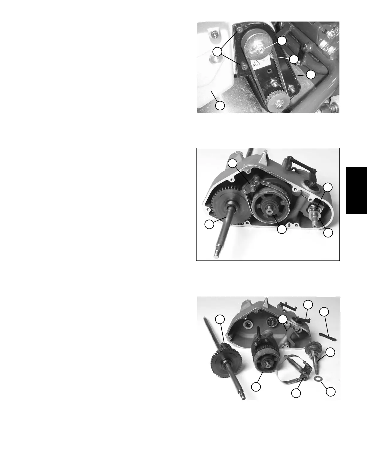
1. Drive shaft plate
2. Socket head screw
3. Cap screw w/lock washer
4. Flange nut
5. Gearbox assembly
Figure 41
2
1
3
4
5
1. Traction shaft with band
2. Planetary assembly
3. Differential assembly
4. Reel drive clutch shaft
5. Clutch thrust washer
Figure 42
1
3
4
5
2
1. Traction shaft with band
2. Planetary assembly
3. Differential assembly
4. Reel drive clutch shaft
5. Clutch thrust washer
6. Link
7. Clutch fork shaft
8. Clutch fork
Figure 43
5
3
6
8
7
4
1
2
Traction and Reel
Drive System
 Loading...


