Greensmaster Flex 21
Page 6 – 5
Chassis and Controls
Handle Removal
1. Park mower on a level surface. Make sure engine is
OFF. Remove high tension lead from the spark plug.
2. Cut cable ties that secure cables.
3. Disconnect:
A. Reel control and traction cables from gearbox
(see Cable Replacement in this Chapter).
B. Parking brake cable from brake bracket assem-
bly (see Cable Replacement in this Chapter).
C. Throttle cable from engine (see Throttle Cable
Replacement in this Chapter).
D. Interlock switch wire connection.
4. Loosen and remove flange nut from cap screw on
each end of the handle (Fig. 4).
5. Remove handle from frame.
Handle Installation
1. Slide handle ends through the holes in the handle
arms with grommets. Install handle to the frame using
cap screw, pivot pin, and flange nut on each side.
2. Attach and adjust:
A. Reel control, traction, and parking brake cables
(see Cable Replacement).
B. Throttle cable (see Throttle Cable Replacement).
C. Interlock switch wire connection.
3. Secure cables with cable ties.
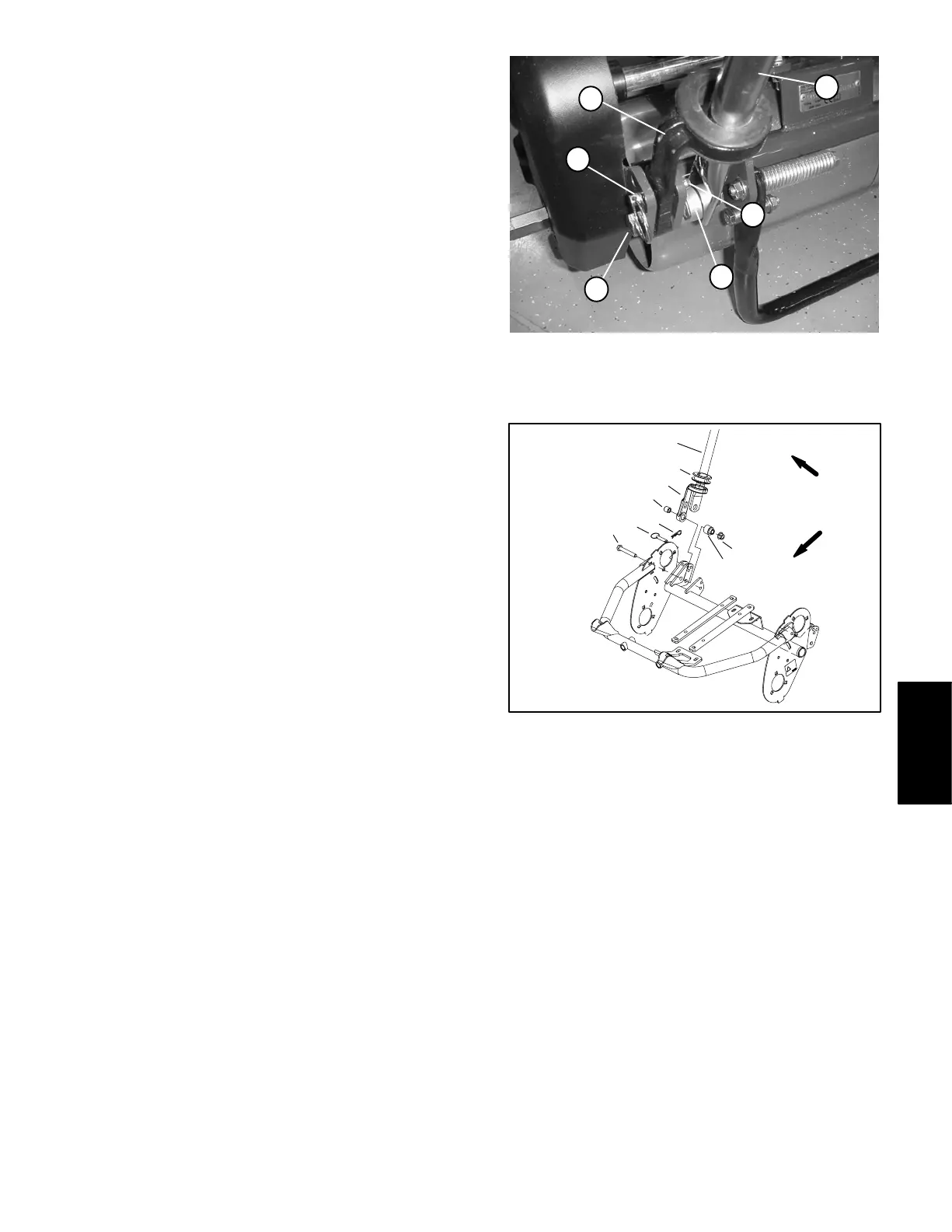
1. Handle end
2. Handle arm w/grommet
3. Hairpin cotter
4. Ring pin
5. Cap screw
6. Pivot pin
Figure 3
6
1
3
5
4
2
1. Handle
2. Handle arm
3. Handle grommet
4. Handle support spacer
5. Pivot pin
6. Flange nut
7. Cap screw
8. Ring pin
9. Hairpin cotter
Figure 4
3
2
4
5
6
9
8
7
1
FRONT
RIGHT
Chassis and
Controls
 Loading...


