ValveAdjustmentRemoval(continued)
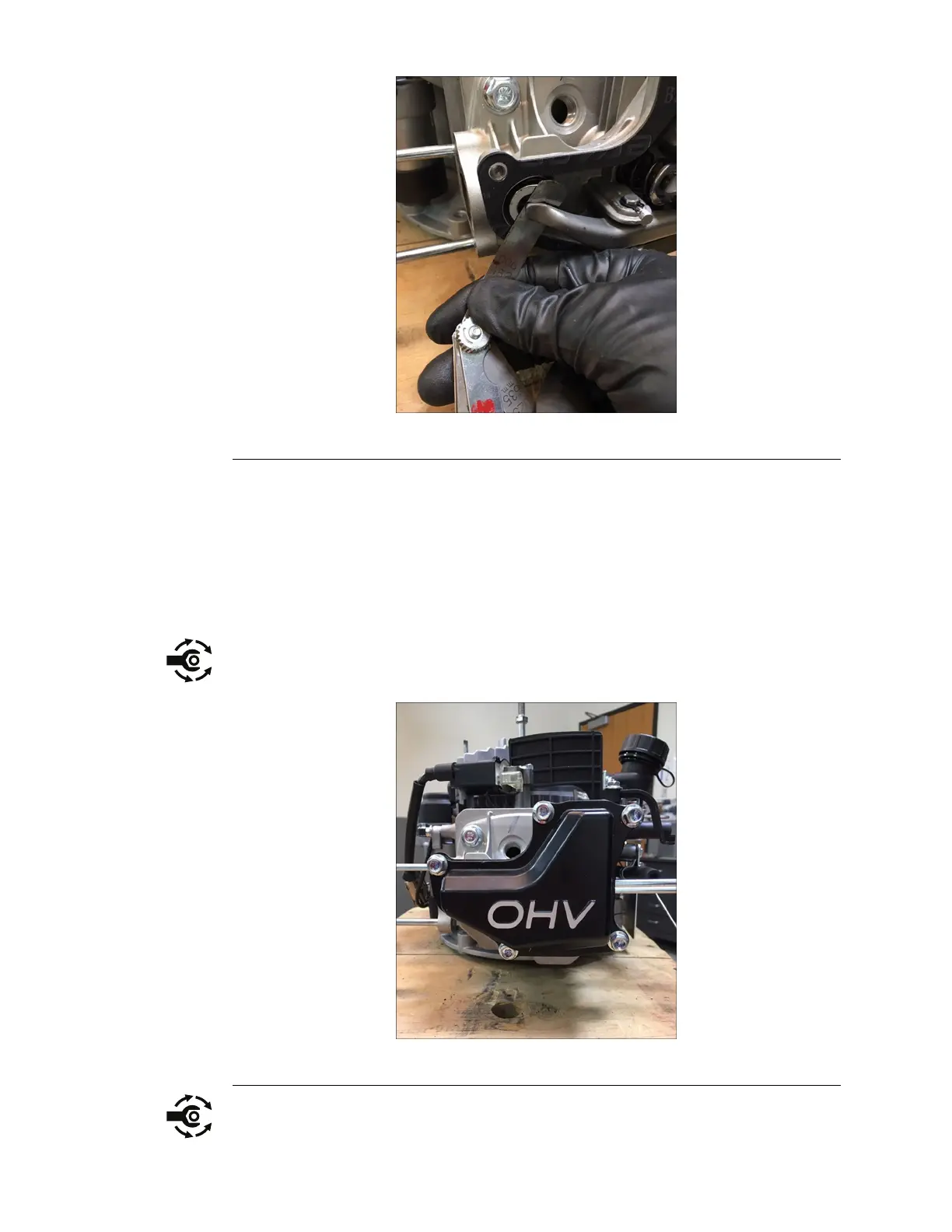
Figure251
11.T omakeanadjustment,placeaatbladescrewdriverintheslotofthe
adjustingscrew.Loosenthelocknutusinga10mmwrench.Turnthe
adjustingscrewinorouttoadjustthegapbetweentherockerarmandvalve
stem.Whentheclearanceiscorrect,tightenthelocknutandrecheckthe
clearance.
ValveAdjustmentInstallation
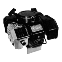
1.Installthevalvecoverontothecylinderhead.
2.Installthe5(10mm)boltssecuringthevalvecovertothecylinderhead.
Torqueboltsto57–87ft-lbs.(6–10Nm).
Figure252
CompressionSystem:ServiceandRepairs
Page7–74
1P65F-2ServiceManual
3429-270RevA