Product Overview
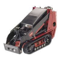
Figure 5
1. Mount
6. Fuel tank
11. Engine
16. Battery
2. Tilt cylinder 7. Wheel 12. Air lter 17. Indicator lights
3. Auxiliary hydraulic couplers 8. Lift cylinder 13. Control panel 18. Tow valves
4. Loader arms 9. Operator platform 14. Lift points 19. Parking brake lever
5. Front access cover
10. Rear access cover (open)
15. Handle
Controls
Become familiar with all the controls ( Figure 6 )
before y ou star t the engine and operate the traction
unit.
Figure 6
1. Traction control levers 5. Speed selector lever
2. Attachment lift lever 6. Throttle lever
3. Loader arm lever 7. Key switch
4. Auxiliary hydraulics lever
8. Hour meter
Key Switch
T he k ey switc h, used to star t and stop the engine ,
has three positions: stop , r un, and star t.
T o star t the engine , rotate the k ey to the star t
position. R elease the k ey when engine star ts and it
will mo v e automatically to the r un position.
T o stop the engine , rotate the k ey to the stop
position.
Throttle Lever
Mo v e the control forw ard to increase the engine
speed and rearw ard to decrease speed.
Traction Control Levers
T o mo v e forw ard, mo v e the traction control lev ers
forw ard. T o mo v e rearw ard, mo v e the traction
control lev ers rearw ard.
T o g o straight, mo v e both traction control lev ers
equally .
T o tur n, mo v e the lev er located on the side y ou
w ant to tur n bac k to w ard the neutral position
while k ee ping the other lev er eng ag ed.
T he far ther y ou mo v e the traction control lev ers
in either direction, the faster the traction unit will
mo v e in that direction.
13
 Loading...