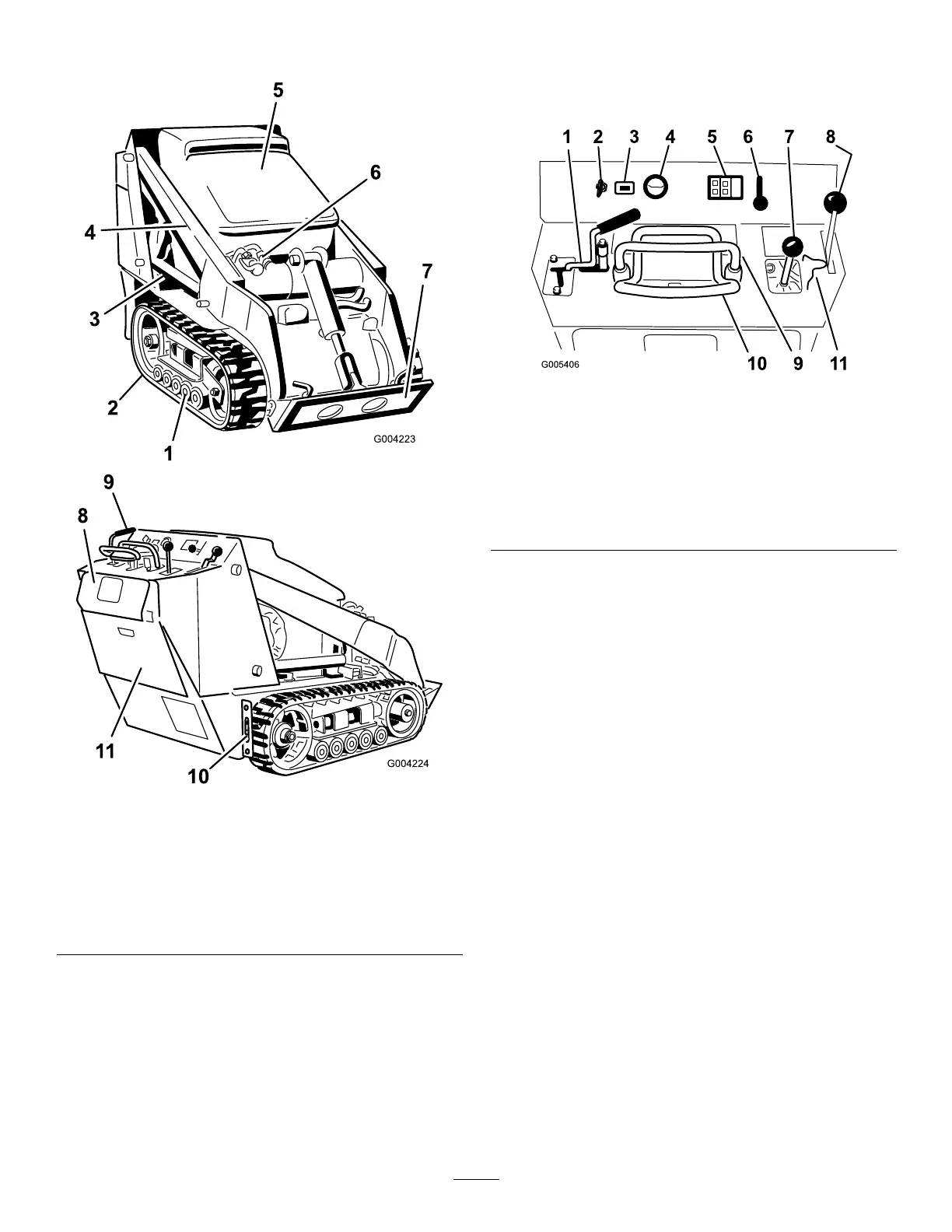
ProductOverview
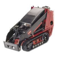
Figure3
1.Roadwheels7.Mountplate
2.Track
8.Reversesafetyplate
3.Liftcylinder9.Controlpanel
4.Loaderarms
10.Tie-down/liftloop
5.Hood11.Rearaccesscover
6.Auxiliaryhydraulic
couplers
Controls
Becomefamiliarwithallthecontrols(Figure4)before
youstarttheengineandoperatethetractionunit.
G005406
12345678
1091 1
Figure4
1.Auxiliaryhydraulicslever
7.Loaderarm/attachmenttilt
lever
2.Keyswitch8.Parkingbrakelever
3.Hourmeter
9.Referencebar
4.Fuelgauge10.Tractioncontrol
5.Indicatorlightsandglow
plugswitch
11.Loadervalvelock
6.Throttlelever
KeySwitch
Thekeyswitch,usedtostartandstoptheengine,has
threepositions:off,run,andstart.
Tostarttheengine,rotatethekeytothestartposition.
Releasethekeywhenenginestartsanditwillmove
automaticallytotherunposition.
Tostoptheengine,rotatethekeytotheoffposition.
ThrottleLever
Movethecontrolforwardtoincreasetheenginespeed
andrearwardtodecreasespeed.
ReferenceBar
Whendrivingthetractionunit,usethereferencebaras
ahandleandaleveragepointforcontrollingthetraction
controlandtheauxiliaryhydraulicslever.Toensure
smooth,controlledoperation,donottakebothhands
offofthereferencebarwhileoperatingthetractionunit.
12