Putthetwoshims(1/8inch[3mm])ontospindle
shaftastheywereoriginallyinstalled.Theseshims
arerequiredtoachievealevelacrosstheentire
widthofthecuttingunits.Slidetheappropriate
numberof1/2inchspacersontothespindleshaft
togetthedesiredheight-of-cut;thenslidethe
washerontotheshaft.
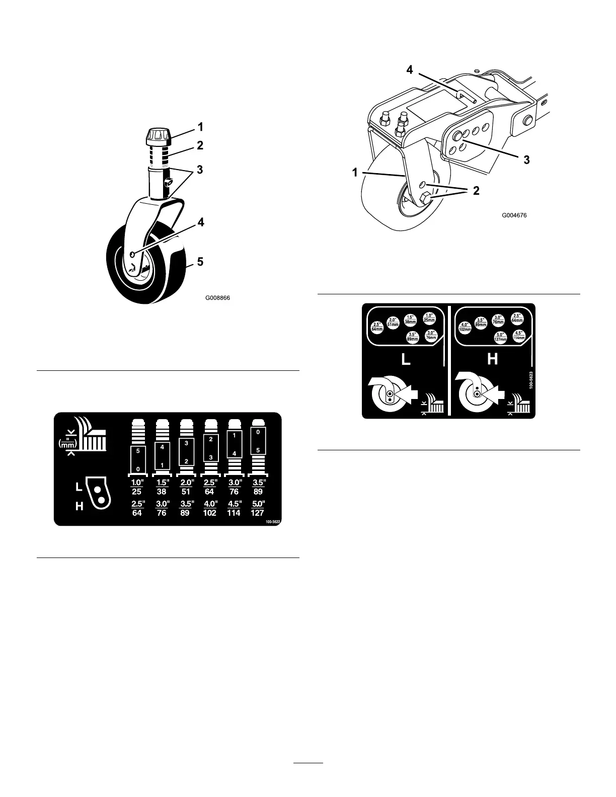
Figure20
1.Tensioningcap4.Toaxlemountinghole
2.Spacers5.Castorwheel
3.Shims
Refertothefollowingcharttodeterminethe
combinationsofspacersforthesetting.
Figure21
3.Pushthecastorspindlethroughthecastorarm.
Installtheshims(asoriginallyinstalled)andthe
remainingspacersontothespindleshaft.Installthe
tensioningcaptosecuretheassembly.
4.Removethehairpincotterandclevispinsfromthe
castorpivotarms(Figure22).
5.Rotatetensionrodtoraiseorlowerpivotarm
untilholesarealignedwithselectedheight-of-cut
bracketholesinthecuttingunitframe(Figure22
andFigure23).
6.Inserttheclevispinsandinstallthehairpincotters.
7.Rotatetensionrodcounterclockwise(ngertight)
toputtensiononadjustment.
Figure22
1.Castorpivotarm3.Clevispinandhairpin
cotter
2.Axlemountingholes4.Tensionrod
Figure23
8.Removethehairpincottersandclevispinssecuring
thedamperlinkstothecuttingunitbrackets
(Figure24).Alignthedamperlinkholeswiththe
selectedheight-of-cutbracketholesinthecutting
unitframe(Figure25),inserttheclevispins,and
installthehairpincotters.
Important:Thedamperlinklengthshould
neverbeadjusted.Thelengthbetweenthehole
centersshouldbe5-3/8inch(13.7cm).
25