Figure26
1.T opttingonkingpin
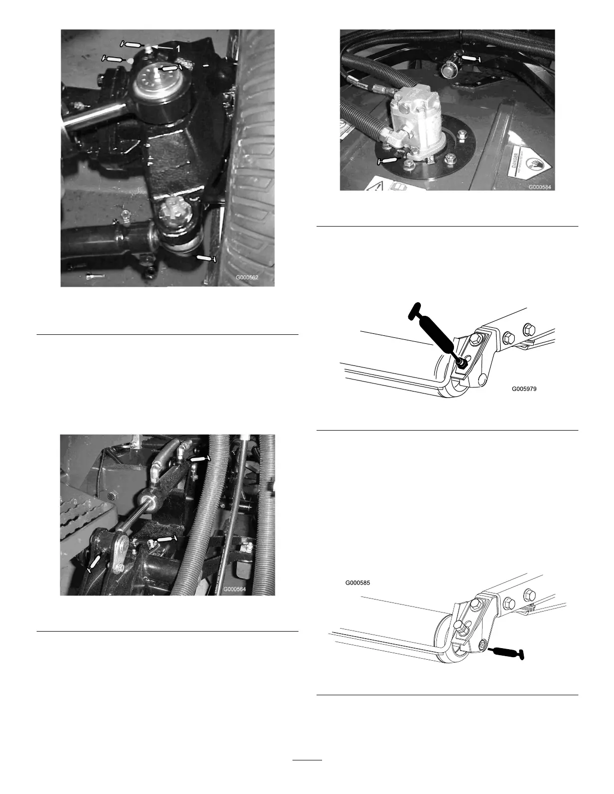
•Tierodballjoints(2)(Figure26)
•Kingpinbushings(2)(Figure26).Thetoptting
onthekingpinshouldonlybelubricated
annually(2pumps).
•Liftarmbushings(1perdeck)(Figure27)
Figure27
•Liftcylinderbushings(2perdeck)(Figure27)
•Cuttingunitspindleshaftbearings(1percutting
unit)(Figure28)
Figure28
•Cuttingunitcarrierarmbushings(1percuttingunit)
(Figure28)
•Rearrollerbearings(2percuttingunit)(Figure29
orFigure30)
Figure29
Important:Makesurethegreasegroovein
eachrollermountalignswiththegreaseholein
eachendoftherollershaft.Tohelpalignthe
grooveandhole,thereisalsoanalignmentmark
ononeendoftherollershaft.
Note:Onrollersequippedwithushgrease
ttings(Figure30)agreasegunnozzleadapteris
required.OrderToroPartNo.107-1998fromyour
AuthorizedToroDistributor.
Figure30
32



 To Next Page