2
CheckingtheTirePressure
NoPartsRequired
Procedure
Thetiresareoverinatedforshipping.Therefore,release
someoftheairtoreducethepressure.Thecorrectair
pressurefornon-cabmodelsis103kPa(15psi)inthefront
tiresand172kPa(25psi)inthereartires.Ifacabisinstalled
onthemachine,thefrontandreartiresshouldbeinatedto
172kPa(25psi).
3
CheckingtheFluidLevels
NoPartsRequired
Procedure
1.Checkthehydraulicuidlevelbeforestartingthe
engine,refertoCheckingtheHydraulicSystem(page
44).
2.Checktheengineoillevelbeforestartingtheengine,
refertoCheckingtheEngine-OilLevel(page34).
3.Checkthecoolingsystembeforestartingtheengine;
refertoCheckingtheCoolingSystem(page39).
4
InstallingtheDriveShafttoan
OptionalMowerDeckorQAS
Partsneededforthisprocedure:
1
Driveshaft
4
Screw,5/16x1–3/4inch
4
Locknut,5/16inch
2
Rollpin,3/16x1–1/2inch
Procedure
Note:PTOdriveshaftinstallationiseasierifthemachineis
positionedonahoist.
1.Parkmachineonalevelsurface,stopengine,engage
parkingbrakeandremovekeyfromtheignitionswitch.
WARNING
Donotstarttheengineandengagethe
PTOswitchwhenthePTOdriveshaftis
disconnectedfromthecuttingdeck.Ifthe
engineisstartedandthePTOshaftisallowed
torotate,seriouspersonalinjuryandmachine
damagecouldresult.BeforethePTOdrive
shaftisdisconnectedfromthecuttingdeck,
disconnectPTOsolenoidcoilconnector
fromwireharnesstopreventunintentional
engagementofthePTOclutch.
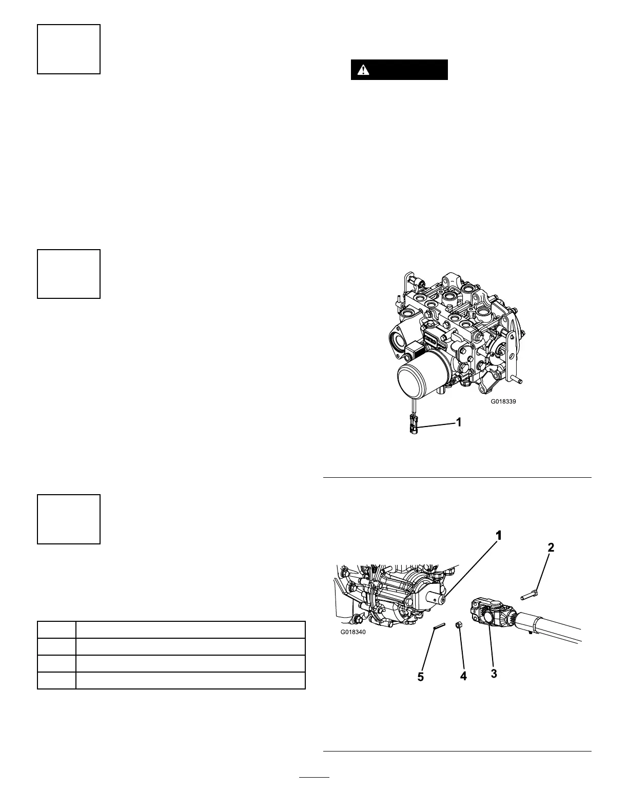
2.TopreventtheunintentionalengagementofthePTO
clutch,disconnectthewireharnesselectricalconnector
fromthePTOsolenoidvalvecoilconnector(Figure4).
Figure4
1.Wireharnesselectricalconnector
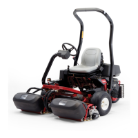
3.PositionthePTOdriveshaftunderthefrontofthe
machine.Makesurethatthedriveshaftslipshaftyoke
(Figure5)istowardthetransmissionPTOshaft.
Figure5
1.Transmissiondriveshaft
4.Locknut
2.Capscrew
5.Rollpin
3.PTOshaft
13