StoppingtheMachine
Tostopthemachine,releasethetractionpedaltotheneutral
position.
Settheparkingbrakewheneveryouleavethemachine.
Remembertoremovethekeyfromtheignitionswitch.
CAUTION
Childrenorbystandersmaybeinjuredifthey
attempttomoveoroperatethetractorwhileitis
unattended.
Alwaysremovetheignitionkeyandsettheparking
brakewhenleavingthemachineunattended,even
ifjustforafewminutes.
OperatingtheMower
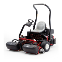
RaisingandLoweringtheMower
Thedeckliftswitchraisesandlowersthemowerdeck(Figure
13).Theenginemustberunningforyoutousethisswitch.
Figure13
1.Deckliftswitch
•Tolowerthemowerdeck,pushtheswitchforward.
•Toraisethemoverdeck,pushtheswitchrearward.
Important:Donotcontinuetoholdtheswitchback
afterthemowerhasfullyraised.Doingsowilldamage
thehydraulicsystem.
Note:Tolockthemowerdeckinaraisedposition,raisethe
deckpastthe15cm(6inch)position,removetheheightof
cutstoppin(refertoAdjustingtheHeight-of-Cut(page20),
andplacethepininthe15cm(6inch)height-of-cutposition
(Figure15).
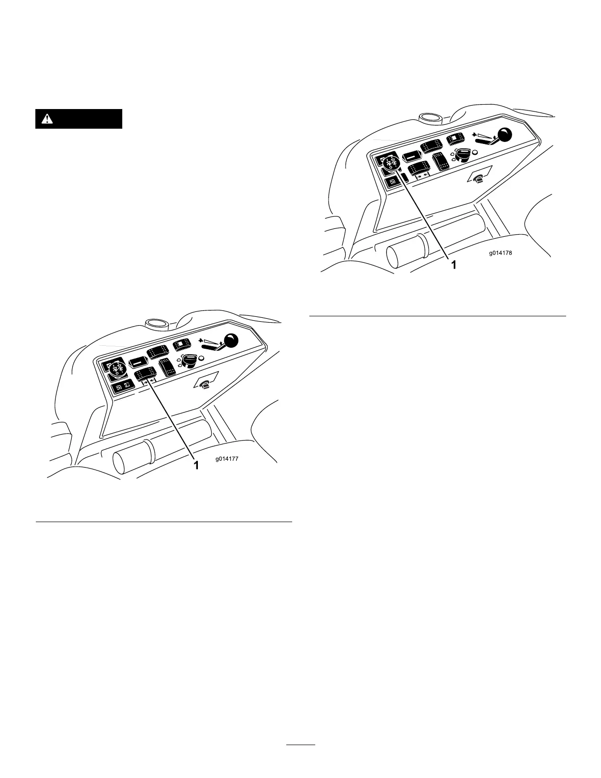
EngagingthePowerTake-off(PTO)
Thepowertake-off(PTO)switchstartsandstopsthemower
bladesandsomepoweredattachments.
1.Iftheengineiscold,allowtheenginetowarmup5to
10minutesbeforeengagingthePTO.
2.Whileseatedintheseat,makesurethetractionpedalis
intheNeutralpositionandtheengineisatfullthrottle.
3.PulluponthePTOswitchtoengageit(Figure14).
Figure14
1.PTOswitch
DisengagingthePTO
Todisengage,pushthePTOswitchtotheOffposition.
AdjustingtheHeight-of-Cut
Theheight-of-cutisadjustedfrom2.5to15.8cm(1to
6inches)in6mm(1/4inch)incrementsbyrelocatingthe
stoppinintodifferentholelocations.
1.Withtheenginerunning,pushbackonthedecklift
switchuntilthemowerdeckisfullyraisedandrelease
theswitchimmediately(Figure15).
2.Toadjust,rotatethestoppinuntilthenubonitlines
upwiththeslotsintheholesintheheight-of-cut
bracketandremoveit(Figure15).
3.Selectaholeintheheight-of-cutbracketcorresponding
totheheight-of-cutdesired,insertthepin,androtateit
downtolockitinplace(Figure15).
Note:Thereare4rowsofholepositions(Figure15).
Thetoprowgivesyoutheheightofcutlistedabovethe
pin.Thesecondrowdowngivesyoutheheightlisted
plus6mm(1/4inch).Thethirdrowdowngivesyou
theheightlistedplus12mm(1/2inch).Thebottom
rowgivesyoutheheightlistedplus18mm(3/4inch).
Forthe15.8cm(6inch)positionthereisonly1hole,
locatedinthesecondrow.Thisdoesnotadd6mm
(1/4inch)tothe15.8cm(6inch)position.
20