ELECTRICAL
6-1
Toro 30” Aerator Service Manual
6
CAUTION
Before performing any tests with a continuity light or
ohmmeter, disconnect the component from the wire
harness. This ensures you are testing the component
rather than another circuit.
Ignition Switch
Purpose
The ignition switch provides the proper switching for the
starter, ignition, accessories, and safety circuits.
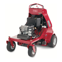
Location
The ignition switch is located on the control panel (Fig.
223).
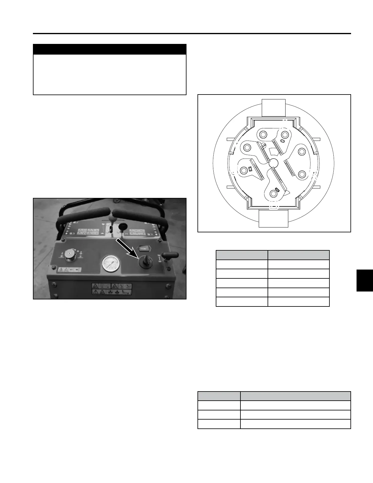
How It Works
Detents inside the switch gives it 3 positions: OFF,
RUN, and START. The START position is spring loaded
so the cylinder automatically returns to RUN once the
key is released (Fig. 224).
Fig. 223 control panel
Fig. 224 ignition switch
Testing
1. Disconnect the switch from the wiring harness.
2. Verify that continuity exists between the terminals
listed for the switch positions (see table). Verify that
there is NO continuity between the terminals not
listed for the switch position (see table).
Position Circuit “Make”
1. OFF None
2. RUN B + R + I + A
3. START B + R + I + S
Terminal Component
A Accessory
R Rectier
B Battery
S Start
I Ignition
A
R
B
S
I
 Loading...