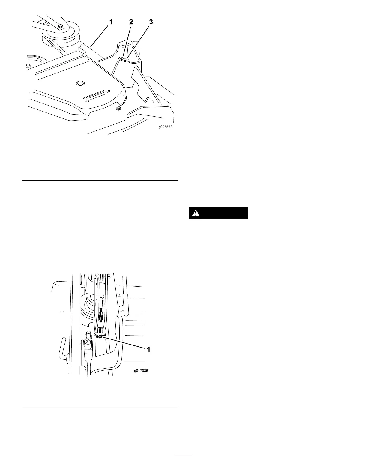
g025558
Figure116
Rear-DischargeMachinesOnly
1.Mowerdeck3.Backhole
2.Fronthole
12.Ifthedeckistoolow,tightenthe
single-point-adjustmentboltbyrotatingit
clockwise.Ifthedeckistoohigh,loosen
thesingle-point-adjustmentboltbyrotatingit
counterclockwise(Figure117).
Note:Loosenortightenthesingle-point
adjustmentboltenoughtomovethe
height-of-cutplatemountingboltsatleast1/3
thelengthoftheavailabletravelintheirslots.
Thisregainssomeupanddownadjustmenton
eachofthe4decklinks.
g017036
Figure117
1.Single-pointadjustmentbolt
13.Tightenthe2boltsatthebottomofthe
height-of-cutplate(Figure115).
Note:Inmostconditions,thebackbladetip
shouldbeadjusted6.4mm(1/4inch)higher
thanthefront.
14.Torquethe2boltsto37to45N∙m(27to33ft-lb).
15.Onbothsidesofthedeck,measurefromthe
levelsurfacetothebacktipoftheblade(postion
B)asshowninFigure113.
Note:Themeasurementshouldread8.3cm
(3-1/4inches)
16.Finetunethescrewadjusterbyturningittoget
8.3mm(3-1/4inches)height(Figure114).
Toincreasetheheight,turntheadjustmentnut
clockwise;todecrease,turncounterclockwise.
17.Measureuntilall4sidesarethecorrectheight.
18.Tightenallofthenutsonthedeck-lift-arm
assemblies.
19.Lowerthedischargechute.
RemovingtheMowerDeck
Lockoutthespring-loadeddeckarmsbeforeservicing
orremovingthemowerdeck.
WARNING
Deck-liftarmassemblieshavestoredenergy.
Removingthedeckwithoutreleasingthe
storedenergycancauseseriousinjuryor
death.
Donotattempttodisassemblethedeckfrom
thefrontframewithoutlockingoutthestored
energy.
1.Parkthemachineonalevelsurface,disengage
theblade-controlswitch(PTO),andengagethe
parkingbrake.
2.Shutofftheengine,removethekey,andwait
forallmovingpartstostopbeforeleavingthe
operatingposition.
3.Placetheheightadjustmentpininthe7.6cm(3
inch)cutting-heightlocation.
Note:Thislocksthedeck-liftarmsinthelowest
positionwhenthedeckisremovedandthe
storedenergyinthedeckspringisreleased.
4.Removethebeltcovers.
5.Liftuptheoorpanandinsertaratchetinto
thesquareholeinthedeckidler(Figure118or
Figure119).
6.Rotatethedeckidlerclockwise,liftuponthe
belt-guidetab(rear-dischargemachinesonly),
andremovethemowerbelt(Figure118or
Figure119).
76