ControlsSystem
Maintenance
Adjustingthe
Control-HandlePosition
Thereare2heightpositionsforthecontrol
levers—highandlow.Removetheboltstoadjustthe
heightfortheoperator.
1.Parkthemachineonalevelsurface,disengage
theblade-controlswitch,andengagetheparking
brake.
2.Shutofftheengine,removethekey,andwait
forallmovingpartstostopbeforeleavingthe
operatingposition.
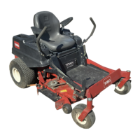
3.Loosentheboltsandangenutsinstalledinthe
levers(Figure63).
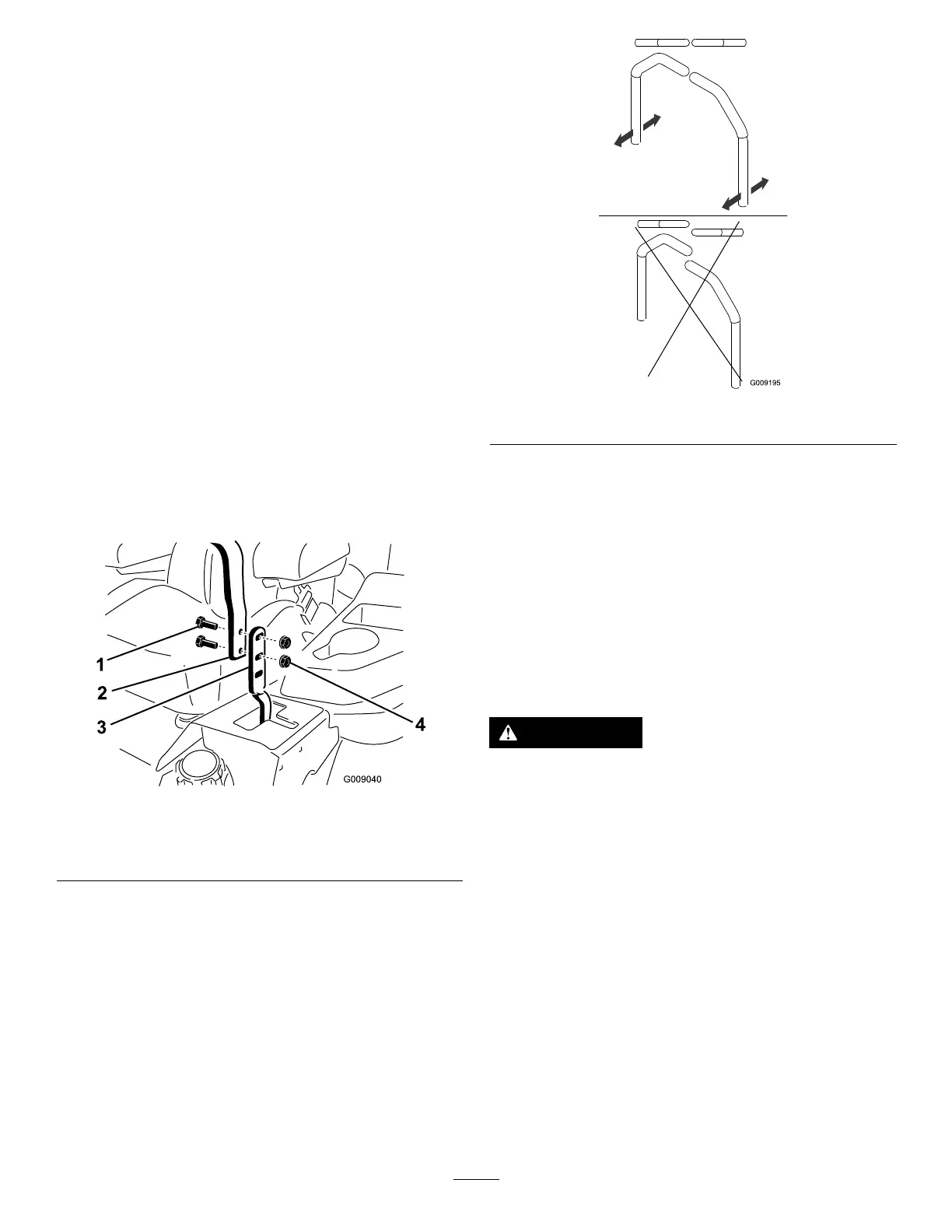
4.Aligntheleversinthefront-to-rearpositionby
bringingtheleverstogethertotheNEUTRAL
position,andslidethemuntiltheyarealigned,
thentightenthebolts(Figure64).
g009040
Figure63
1.Bolt
3.Controllever
2.Handle4.Nut
g009195
Figure64
5.Iftheendsofthelevershitagainsteachother,
repeatthisprocedure.
Adjustingthe
Motion-ControlLinkage
Locatedoneithersideofthefueltank,belowtheseat
arethepump-controllinkages.Rotatingthepump
linkagewithawrench(1/2inch)allowsnetuning
adjustmentssothatthemachinedoesnotmovein
neutral.Anyadjustmentsshouldbemadeforneutral
positioningonly.
WARNING
Toadjustthemotioncontrol,youmustrun
theengineandturnthedrivewheels.Contact
withmovingpartsorhotsurfacesmaycause
personalinjury.
Keepyourngers,hands,andclothingclear
ofrotatingcomponentsandhotsurfaces.
1.Priortostartingtheengine,pushthedeck-lift
pedal,andremovetheheight-of-cutpin.
2.Lowerdecktotheground.
3.Raisetherearofmachineupandsupportitwith
jackstands(orequivalentsupport).
Note:Raisethemachinejusthighenoughto
allowthedrivewheelstoturnfreely.
4.Removetheelectricalconnectionfromtheseat
safetyswitch,locatedunderthebottomcushion
oftheseat.
Note:Theswitchisapartoftheseatassembly.
53