2.Shutofftheengine,removethekey,andwait
forallmovingpartstostopbeforeleavingthe
operatingposition.
3.Unlatchtheseatandtipitforward.
4.Loosenthefrontenginepanelknobsand
removethepanel.
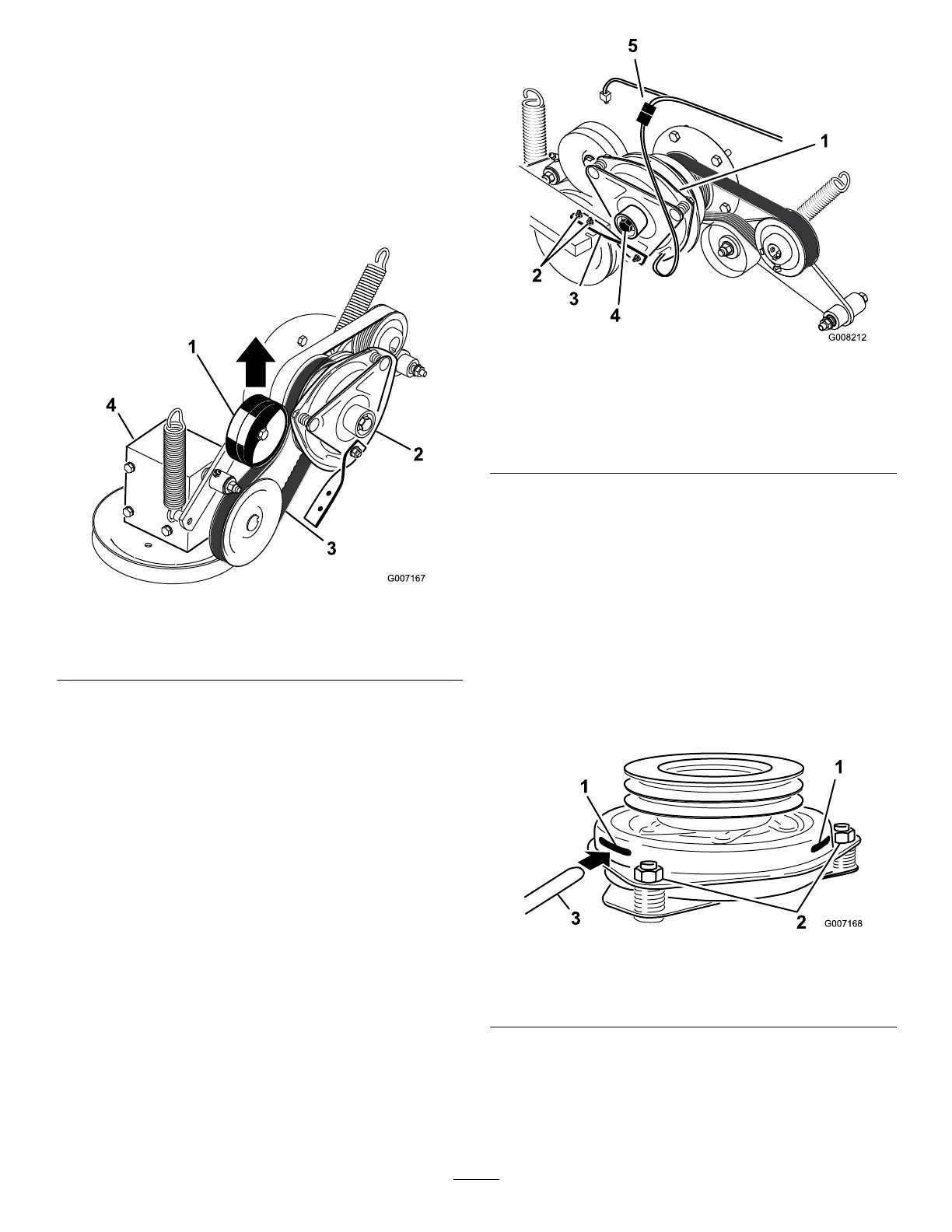
5.Pulluponthespringloadedidlerpulleyforthe
PTOdrivebeltandremovethebeltfromthe
clutchpulley(Figure54).
g007167
Figure54
1.Spring-loadedidlerpulley3.PTOdrivebelt
2.Clutch4.Gearbox
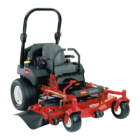
6.Unplugtheelectricconnectionfortheclutch
(Figure55).
7.Removetheboltsholdingtherubberclutchstrap
tothemowerframe(Figure55).
8.Removethecenterboltholdingtheclutchto
theengineshaftandremovetheclutchandkey
(Figure55).
g008212
Figure55
1.Clutch4.Clutchcenterbolt
2.Bolts(2)andnutsfor
clutchstrap
5.Electricalconnection
3.Rubberclutchstrap
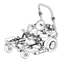
9.Inserta0.381to0.533mm(0.015to0.021inch)
feelergaugethrough1inspectionslotintheside
oftheassembly.Makesureitisbetweenthe
armatureandtherotorfrictionsurfaces(Figure
56).
10.Tightenthelocknutsuntilthereisslightbinding
onthefeelergaugebutitcanbemovedeasily
withintheairgap(Figure56).
11.Repeatthisfortheremainingslots.
12.Checkeachslotagainandmakeslight
adjustmentsuntilthefeelergaugebetween
therotorandarmaturehasveryslightcontact
betweenthem.
g007168
Figure56
1.Slot
3.Feelergauge
2.Adjustingnut
13.Installtheclutchtotheengineshaftwiththekey.
14.Applythread-lockingadhesivetothecenterbolt.
15.Whileholdingthecrankshaftatthebackofthe
machine,installthecenterboltandtorqueitto
68N∙m(50ft-lb)(Figure55).
46