g014973
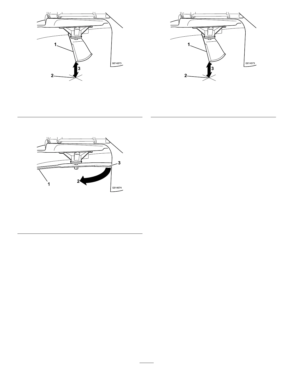
Figure 51
1. Blade (in position for measuring)
2. Level surface
3. Measured distance between blade and the surface (A)
4. Rotate the same blade 180 degrees so that the opposing
cutting edge is now in the same position (Figure 52).
g014974
Figure 52
1. Blade (side previously measured)
2. Measurement (position used previously)
3. Opposing side of blade being moved into measurement
position
5. Measure from the tip of the blade to the at surface
(Figure 53).
Note: The variance should be no more than 3 mm
(1/8 inch).
g014973
Figure 53
1. Opposite blade edge (in position for measuring)
2. Level surface
3. Second measured distance between blade and surface (B)
A. If the difference between A and B is greater than
3 mm (1/8 inch), replace the blade with a new
blade; refer to Removing the Blades (page 41) and
Installing the Blades (page 41).
Note: If a bent blade is replaced with a new
blade, and the dimension obtained continues to
exceed 3 mm (1/8 inch), the blade spindle could
be bent. Contact an Authorized Toro Dealer for
service.
B. If the variance is within constraints, move to the
next blade.
6. Repeat this procedure on each blade.
40